


ENS7003R16 KO65 2013
22
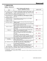
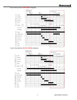
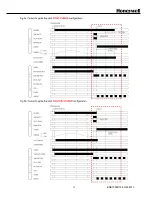
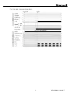
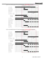
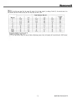
Table 8: Error condition and LED status
Sequence
Error condition
Indicator
LED
status (*1)
All
Safety limits opened at any time (no voltage present at T18 (STD model) or
T19 (ENH/ULT model)
●○○○○○○◐
Standby (*2)
Air flow switch remains ON (closed) for more than 5 minutes, or START position
interlock switch remains OFF(opened) for more than 5 minutes.
●◐○○○○○◐
Flame signal is present
●○○○○○◐◐
Blower motor is energized
●◐○◐◐○○◐
Pre-purge
Air flow switch remains OFF for more than 5 minutes after the heat demand has
started.
●◐○○○○○◐
PURGE position interlock switch remains OFF for more than 5 minutes after the heat
demand started.
●◐◐◐○○○◐
Both PURGE and START position interlocks ON at the same time during prepurge
period
●◐◐◐○○○◐
START position interlock remains OFF more than 5 minutes after pre-purge has
finished
●◐◐◐○○○◐
Air flow switch goes ON within 5 minutes after the heat demand started, but air flow
switch goes OFF again.
●◐○○○○○◐
Flame signal is present.
●◐○○○○◐◐
Ignition Standby
Air flow switch goes OFF
●◐○○○○○◐
Flame signal is present
●◐○○○○◐◐
Pilot Ignition
Air flow switch goes OFF
●◐◐○○○○◐
Ignition failure (flame signal is not present after ignition-trial).
●○◐○○○○◐
Pilot only
Air flow switch goes OFF
●◐○◐○○○◐
No flame signal
●○○◐○○◐◐
Main ignition
Air flow switch goes OFF
●◐○○◐○○◐
No flame signal
●○○○◐○◐◐
Main ignition
Stabilization
Air flow switch goes OFF
●◐○○◐○○◐
No flame signal
●○○○◐○◐◐
Run
Air flow switch goes OFF
●◐○○○◐○◐
No flame signal
●○○○○◐◐◐
Post-purge
No power is supplied to Terminal 3 because of internal relay contact failure.
●◐○◐◐○○◐
Flame signal is present for more than 10 seconds after heat demand has ended.
●○○○○○◐◐
Air flow switch keeps ON more than 5 minutes after post-purge.
●◐○○○○○◐
All
1. Line voltage out of specs for more than 2 seconds
2. Line frequency out of range for more than 2 seconds
3. Excessive noise on power line or in the area
4. Internal device problem: CPU clock out of sync
●○○○○○○●
*1 : For LED indication,
○
means ‘off’,
●
means ‘illuminated’,
◐
means ‘blinking’.
The LEDs are arranged in the following order: Standby, Purge, Ignition, Pilot, Main, Modulate, Flame and Alarm at the left
front side of the DBC2000.
*2 : If an error occurs during Standby, the DBC2000 will not lock-out but LEDs indicate the current error status.
In this case, the DBC2000 cannot start before the error is resolved.
Summary of Contents for DBC2000E10 Series
Page 13: ...ENS7003R16 KO65 2013 13 ...
Page 15: ...ENS7003R16 KO65 2013 15 ...
Page 16: ...ENS7003R16 KO65 2013 16 ...
Page 17: ...ENS7003R16 KO65 2013 17 ...
Page 18: ...ENS7003R16 KO65 2013 18 ...
Page 19: ...ENS7003R16 KO65 2013 19 ...
Page 20: ...ENS7003R16 KO65 2013 20 ...
Page 21: ...ENS7003R16 KO65 2013 21 ...
Page 27: ...ENS7003R16 KO65 2013 27 ...
Page 28: ...ENS7003R16 KO65 2013 28 ...
Page 29: ...ENS7003R16 KO65 2013 29 ...
Page 30: ...ENS7003R16 KO65 2013 30 ...
Page 31: ...ENS7003R16 KO65 2013 31 ...
Page 32: ...ENS7003R16 KO65 2013 32 ...
Page 33: ...ENS7003R16 KO65 2013 33 ...
Page 34: ...ENS7003R16 KO65 2013 34 ...