


ENS7003R16 KO65 2013
3
Table 4: Flame detection systems
Detector
type
Flame detector model no.
Max. lead wire
lengths
Standard stable flame
current on jack plug
UV detector
C7027A, C7035A, C7044A
< 100m
4µA (min)
14µA (max)
Flame rod
Flame rod or rectifying optical sensors,
C7012A,G (UV) or IRD1020.1 (IR)
< 15m
14µA (min)*
4µA (max)*
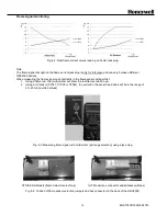
* When using a flame rod, the current on the flame jack plug is inverted. See also Fig 4-2.
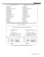
Flame detector leads are colour coded. The blue lead wire must be connected to the F terminal (T23) and the
white lead wire to the G terminal (T24). The UV sensing tube is polarity sensitive. Reversing the lead wires
even momentarily will destroy the UV sensing tube.
Summary of Contents for DBC2000E10 Series
Page 13: ...ENS7003R16 KO65 2013 13 ...
Page 15: ...ENS7003R16 KO65 2013 15 ...
Page 16: ...ENS7003R16 KO65 2013 16 ...
Page 17: ...ENS7003R16 KO65 2013 17 ...
Page 18: ...ENS7003R16 KO65 2013 18 ...
Page 19: ...ENS7003R16 KO65 2013 19 ...
Page 20: ...ENS7003R16 KO65 2013 20 ...
Page 21: ...ENS7003R16 KO65 2013 21 ...
Page 27: ...ENS7003R16 KO65 2013 27 ...
Page 28: ...ENS7003R16 KO65 2013 28 ...
Page 29: ...ENS7003R16 KO65 2013 29 ...
Page 30: ...ENS7003R16 KO65 2013 30 ...
Page 31: ...ENS7003R16 KO65 2013 31 ...
Page 32: ...ENS7003R16 KO65 2013 32 ...
Page 33: ...ENS7003R16 KO65 2013 33 ...
Page 34: ...ENS7003R16 KO65 2013 34 ...