


TITLE
Model
DOCUMENT NO.
PAGE
CK75 Repair Manual
CK75
L3-GLBL-RPR-4254
(Rev A)
Page
37
of
42
L3-GLBL-RPR-4516 (Rev A)
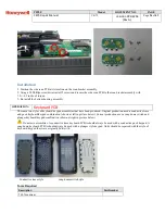
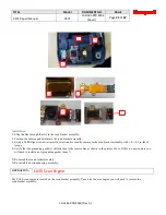
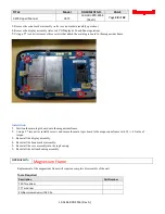
Installation is reverse order of removal.
1.
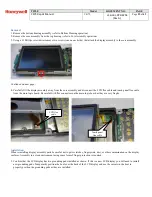
Verify that a piece of kapton tape and a foam pad are still in place on the scan flex cable. If they are not or this is a new flex
cable they will need to be installed as shown in the above picture.
2.
Verify that a piece of kapton tape is in place on the scan engine. If it is not or this is a new scan engine it will need to be
installed as shown in the above picture.
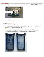
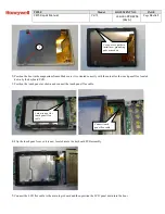
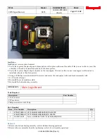
3.
Using a #0 Phillips screwdriver install two screws and secure the scan engine to the scan bracket assembly with
1.2+/-0.2 in-lbs of torque.
4.
Re-install the scan bracket assembly.
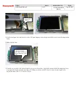
5.
Re-install the bottom housing assembly.
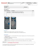
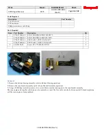
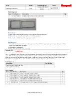
OPERATION:
Main Logic Board
Tools Required
Description
Part Number
T10 Torx driver
T7 Torx driver
Phillips screwdriver with #0 tip
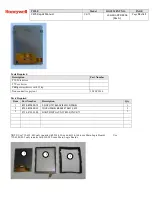
Parts Required
Item
Part Number
Description
Qty
1
8754-870900-14 CK75 WLAN MAINBOARD WITH HEATER
1
8754-870900-98 CK75 WLAN MAINBOARD W/O HEATER
1
2
48-352753-01
Screw,
UNC#2-56*0.125",T7,WFR,SS,NO,NYLOK
4
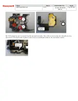
Removal
1.
Remove the bottom housing assembly (refer to Bottom Housing operation).
2.
Remove the core assembly from the top housing (refer to Core Assembly operation).
Installation


