


TITLE
Model
DOCUMENT NO.
PAGE
CK75 Repair Manual
CK75
L3-GLBL-RPR-4254
(Rev A)
Page
19
of
42
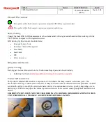
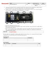
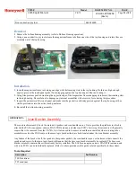
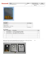
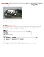
OPERATION:
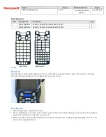
Vibrator Motor
The vibrator motor is friction fit into the bottom housing assembly. A cable then connects it to the keyboard PCB assembly.
Tools Required
Description
Part Number
Tweezers
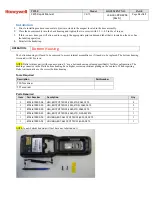
Parts Required
Item
Part Number
Description
Qty
1
8754-870903-05
Vibrator,3V,70mA,w/Wire,CK75
1
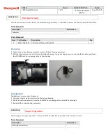
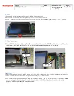
Removal
1.
Remove the bottom housing assembly (refer to Bottom Housing operation).
2.
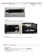
Pull the vibrator motor out of its slot in the bottom housing. A piece of kapton tape is used to hold the cable away from
the uSD/SIM card door opening in the bottom housing.
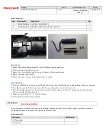
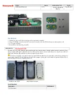
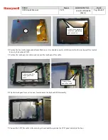
Installation
Installation is reverse order of removal.
1.
Press the vibrator motor into its slot in the bottom housing.
2.
Route the cable around away from the uSD/SIM door opening and re-install the kapton tape.
3.
Re-install the bottom housing assembly.
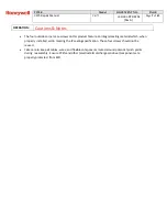
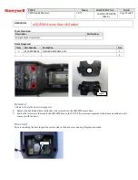
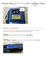
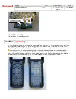
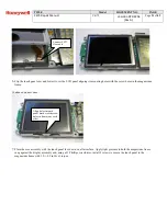
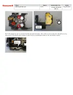
OPERATION:
Super Capacitor
The backup power super capacitor is secured inside the bottom housing with a bracket and two screws.
Tools Required
Description
Part Number
#0 Phillips Screwdriver
1


