


TITLE
Model
DOCUMENT NO.
PAGE
CK75 Repair Manual
CK75
L3-GLBL-RPR-4254
(Rev A)
Page
34
of
42
L3-GLBL-RPR-4516 (Rev A)
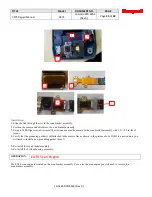
Installation
Installation is reverse order of removal.
1.
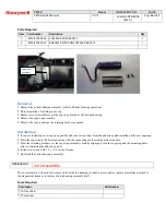
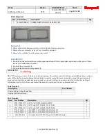
Position the WAN antenna onto the scan bracket assembly.
2.
Using a #1 Phillips screwdriver install 3 screws and secure the WAN antenna to the scan bracket assembly with
2.5+/-0.2 in-lbs of torque.
3.
Re-install the scan bracket assembly.
4.
Re-install the bottom housing assembly.
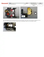
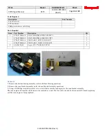
OPERATION:
Camera
The camera is located on the scan bracket assembly. To service the camera you will need to remove the scan bracket assembly.
Tools Required
Description
Part Number
T10 Torx driver
T7 Torx driver
Phillips screwdriver with #1 tip
Parts Required
Item
Part Number
Description
Qty
1
850-583-001
CAMERA MODULE ASSY, 5MPIXEL,AUTOFOCUS
1
2
8754-870903-03
SHIELD,CAMERA,SUS304,CK75
1
3
8754-870903-04
SPACER,CAMERA LED,PORON,CK75
1
4
8754-870901-01
TAPE,KAPTON,24.4MM*5MM,CNCK75
1
5
8754-870900-11
FLEX CABLE,CAMERA,CK75
1
6
8754-870900-06
HOLDER,CAMERA FLEX,SUS304,CNCK75
1
7
8754-870903-02
CONDUCTIVE FABRIC,CAMERA FLEX,CK75
1
48-454675-01
Screw, ST1.4*0.45*2.3,PH,PAN,ST,NB
4
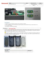
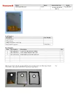
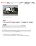
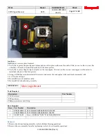
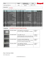
** units without a camera but with a WAN radio will have this blank metal piece installed in place of a camera. Units without a
camera and without a WAN radio will have nothing installed in the camera location.
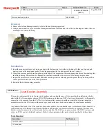
Removal
1.
Remove the bottom housing assembly (refer to Bottom Housing operation).
2.
Remove the scan bracket assembly (refer to Scan Bracket Assembly operation).
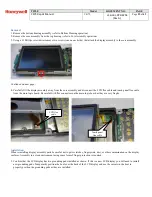
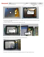
3.
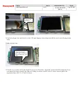
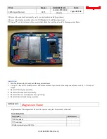
Using a #0 Phillips screwdriver remove four screws that secure the camera to the scan bracket assembly.
The camera shield and camera can now be removed. Compress the grounding gasket on the back of the flex cable to slide the
flex through the slot in the scan bracket assembly.


