background image


Table of Contents 


 Title 

Page 

Introduction............................................................................................................................................ 1


Contacting BW Technologies................................................................................................................ 2


Safety Information - Read First ............................................................................................................. 2


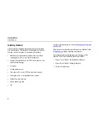
Getting Started ...................................................................................................................................... 6


Parts of the GasAlertMicro Detector ..................................................................................................... 7


Installing Alkaline Batteries ................................................................................................................. 10


Activating the Detector........................................................................................................................ 10


Self-Test...............................................................................................................................10


Self-Test Pass ..................................................................................................................... 14


Self-Test Fail........................................................................................................................ 14


Battery Test.......................................................................................................................... 14


Datalogger Operation (optional) .......................................................................................... 14


Deactivating the Detector.................................................................................................................... 15


Confidence Beep................................................................................................................................. 15


User Options Menu ............................................................................................................................. 16


Software Level ..................................................................................................................... 17


Finish Options...................................................................................................................... 17


Latching Alarms ................................................................................................................... 17


Safe Display......................................................................................................................... 18


Combustible Sensor Measuring Selection .......................................................................... 19


French.................................................................................................................................. 21


German ................................................................................................................................ 21


Spanish ................................................................................................................................ 22


i


Summary of Contents for BW GasAlertMicro

Page 1: ...asAlertMicro 1 2 3 and 4 Gas Detectors D2067 6 English iERP 117754 BW Technologies 2006 All rights reserved Printed in Canada All product names are trademarks of their respective companies H2S CO O2 SO2 Combustibles ...

Page 2: ...pplicable recommendations of BW b the buyer promptly notifying BW of any defect and if required promptly making the product available for correction No goods shall be returned to BW until receipt by the buyer of shipping instructions from BW and c the right of BW to require that the buyer provide proof of purchase such as the original invoice bill of sale or packing slip to establish that the prod...

Page 3: ...lling Alkaline Batteries 10 Activating the Detector 10 Self Test 10 Self Test Pass 14 Self Test Fail 14 Battery Test 14 Datalogger Operation optional 14 Deactivating the Detector 15 Confidence Beep 15 User Options Menu 16 Software Level 17 Finish Options 17 Latching Alarms 17 Safe Display 18 Combustible Sensor Measuring Selection 19 French 21 German 21 Spanish 22 i ...

Page 4: ...Mode 31 Bump Due Reminder 32 Adjust Clock 33 Logger Rate 34 Alarms 35 Gas Exposures Computed 38 Viewing Gas Exposures 38 Gas Alarm Setpoints 39 Resetting Gas Alarm Setpoints 39 Stopping a Gas Alarm 39 Sensor Alarm 40 Low Battery Alarm 40 Automatic Shutdown Alarm 40 Calibration and Setting Alarm Setpoints 40 Calibration Guidelines 40 Diagnostics Protection 41 Attaching the Gas Cylinder to the Detec...

Page 5: ...Import to Compatible Programs 52 Determining Application Compatibility 53 Descriptions of Line Examples 56 Maintenance 56 Inserting the MultiMediaCard MMC 57 Replacing the Batteries 57 Replacing a Sensor or Sensor Filter 59 Troubleshooting 62 Replacement Parts and Accessories 65 Specifications 69 iii ...

Page 6: ...GasAlertMicro User Manual iv ...

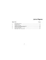
Page 7: ... 7 Computed Gas Exposures 38 8 Gas Alarm Setpoints 39 9 Sample Factory Set Alarm Setpoints 39 10 Attaching the Gas Cylinder to the Detector 42 11 Datalogger Status Codes 54 12 CSV File Example 55 13 Replacing the Batteries 58 14 Torque Specs 60 15 Replacing a Sensor or Sensor Filter 60 16 Troubleshooting Tips 62 17 Replacement Parts and Accessories 65 v ...

Page 8: ...GasAlertMicro User Manual vi ...

Page 9: ... GasAlertMicro Detector 7 2 8 Display Elements 3 10 Installing the Batteries 4 42 Attaching the Gas Cylinder to the Detector 5 57 Inserting the MultiMediaCard MMC 6 58 Replacing the Batteries 7 61 Replacing a Sensor or Sensor Filter vii ...

Page 10: ...ntinuous datalogging while the instrument is operating Data is saved on a convenient MultiMediaCard MMC and can be removed and downloaded by the user Data is imported into standard office software Microsoft Excel Access etc Wraparound memory ensures the most recent data is always saved Accessing Test Results with Fleet Manager To access and view test results using the Fleet Manager software applic...

Page 11: ...tor is a personal safety device It is your responsibility to respond properly to the alarm Table 1 lists the gases that are monitored Table 1 Gases Monitored Gas Detected Unit of Measure Hydrogen sulfide H2S parts per million ppm Carbon monoxide CO parts per million ppm Oxygen O2 percent by volume Combustible gases field selectable for a percent of lower explosive limit LEL b percent by volume met...

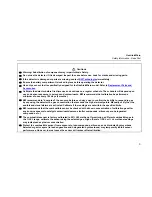
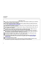
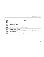
Page 12: ...t www gasmonitors com ISO 9001 Safety Information Read First Use the detector only as specified in this manual otherwise the protection provided by the detector may be impaired International symbols used on the detector and in this manual are explained in Table 2 Read the Warnings and Cautions on the following pages before using the detector ecNote This instrument contains batteries Do not mix wit...

Page 13: ...s use to confirm their ability to respond to gas by exposing the detector to a gas concentration that exceeds the high alarm setpoints Manually verify that the audible and visual alarms are activated Calibrate if the readings are not within the specified limits BW recommends that the combustible sensor be checked with a known concentration of calibration gas after any known exposure to catalyst co...

Page 14: ... shock or other forms of personal injury and property damage Extended exposure of the GasAlertMicro to high concentrations of combustible gases and air may stress a detector element which can seriously affect its performance If an alarm occurs due to high concentration of combustible gases recalibrate immediately If required replace the sensor Do not test the combustible sensor response with a but...

Page 15: ...European Explosives Protection X Conforms to European Union Directives BAM BAM performance verification to European Performance Standards ATEX Conforms to European ATEX Directives IECEx International Electrotechnical Commission Scheme for Certification to Standards for Electrical Equipment for Explosive Atmospheres Type approved by ABS America for use aboard cargo vessels 5 ...

Page 16: ...att charger O2 sensor Combustible sensor Four gas units one H2S CO sensor dual sensor Three gas units one applicable toxic sensor Calibration hose and cap Quick reference guide CD To order replacement parts refer to Replacement Parts and Accessories Each detector is manufactured with sensors installed Refer to Maintenance before installing the batteries For information about the features and funct...

Page 17: ...the GasAlertMicro Detector Figure 1 GasAlertMicro Detector Table 3 GasAlertMicro Detector Item Description 1 Audible alarms 2 Visual alarm bars 3 Sensors 4 Pushbuttons 5 Display 6 Battery compartment 7 Datalogger optional 8 Alligator clip 7 ...

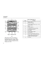
Page 18: ...with the auto backlight option enabled Table 4 Display Elements Item Function 1 Alarm condition 2 Battery life indicator 3 Button indicator displays when a button press is allowed 4 Clock 5 Gas identifier bars 6 Datalogger card indicator optional 7 Automatically zero sensor 8 Gas cylinder 9 Automatically span sensor 10 Pass code lock 11 Real time calendar date month year 12 Alarm condition low hig...

Page 19: ...isplayed value or to scroll up press G To enter the user options menu press G and H simultaneously and hold for 5 seconds To clear the TWA STEL and MAX gas exposure readings press C and G simultaneously To quickly scroll through options press and hold G H To decrement a displayed value or scroll down press H To initiate calibration and enter alarm setpoints press C and H simultaneously and hold fo...

Page 20: ...y markings are shown inside the battery tray 4 Insert the battery tray into the detector Push until the release tabs click Activating the Detector To activate the detector and only in an area that is free from hazardous gases 20 9 oxygen press A Self Test When the detector is activated it performs several system tests Verify that all tests have been performed prior to using the detector The follow...

Page 21: ...All of the display elements briefly turn on during start up 3 Date Test optional This test displays the day of the week 1 7 the time hour minutes and the date day month year 4 Backlight Test The backlight turns on and then off 5 Alarm Setpoints Test The TWA STEL low and high alarm setpoints display Note Alarm setpoints can vary according to region For more information refer to Resetting Gas Alarm ...

Page 22: ...nabled to remind when a bump check is due If this feature is enabled and bump check is due the LCD displays the following screens The detector beeps twice flashes once and emits one vibration 1 To temporarily bypass the reminder hold the C button for two seconds Note Bypassing the reminder is temporary The reminder will display and alarm the next time the detector is activated 2 To bump the detect...

Page 23: ...r has failed Sensor 1 CO H2S or SO2 Sensor 2 LEL Sensor 3 Oxygen 9 MultiMediaCard MMC Test optional If there is no MMC card installed the LCD displays a scrolling error message The card is not required for operation the message is a reminder only 10 Oxygen Sensor Test Unless this feature is disabled the oxygen sensor is calibrated automatically If the automatic oxygen calibration feature has been ...

Page 24: ...il If the detector fails the self test refer to Troubleshooting Battery Test The detector tests the batteries upon activation and continuously thereafter The battery power icon I displays at all times while in normal operation mode If the battery voltage is low the detector displays the low battery icon LOW and activates the low battery alarm beeps every 10 seconds if the confidence beep is disabl...

Page 25: ...ys the detector will remain activated Confidence Beep The confidence beep is used to confirm that the detector is activated and the batteries have sufficient power to respond to a hazardous level of gas When battery power is sufficient the audible alarm beeps twice every 15 seconds The confidence beep stops when battery power is too low The confidence beep can be enabled or disabled To enable disa...

Page 26: ...seconds until the LCD displays USEr OPtionS Following the USEr OPtionS screen the FiniSh OPtionS screen immediately displays NOTE If the detector is pass code protected when USEr OPtionS is entered the LCD displays an error message Refer to Pass Code Protection to enter a pass code 2 Press H or G to scroll through the options Press and hold H or G to scroll through the options quickly 3 Press C to...

Page 27: ...el The software level provides information about the firmware and the EEPROM version of the detector To view information about the firmware and EEPROM version complete the following From the user options menu press A For more information refer to the Specifications Finish Options FiniSh OPtionS displays after accessing the USEr OPtionS menu after each user option function is completed and is used ...

Page 28: ...d return to normal operating mode Safe Display The SAFE dISPLAY option automatically notifies that only normal ambient conditions exist and that there are no gas hazards monitored This option can be enabled or disabled If this option is enabled when the detector is in normal operating mode and when no hazards are measured SAFE scrolls across the LCD continually SAFE does not display while function...

Page 29: ...ew user option or press C to exit user options and return to normal operating mode Combustible Sensor Measuring Selection The LEL SEn unitS option is used to select how the measurements are displayed The options are 0 100 LEL or 0 5 0 vol Note The detector is shipped with the combustible sensor set to measure and display combustible gases in the 0 100 LEL lower explosive limit range The detector c...

Page 30: ... SEn unitS option 2 Press C to select the option An LEL current mode screen immediately displays either vol or or PErcEnt bY vol units are displayed by volume PErcEnt LEL units are displayed by percent The LCD returns to the FiniSh OPtionS screen 3 Use G or H to scroll to a new user option or press C to exit user options and return to normal operating mode 20 ...

Page 31: ...n 3 Use G or H to scroll to a new user option or press C to exit user options and return to normal operating mode German The AnZEigE dEutSch option is used to convert all of the LCD screens to display German text 1 From the user options menu use G or H to scroll to the AnZEigE dEutSch option 2 Press C to select the option The LCD automatically displays German text and returns to the FiniSh OPtionS...

Page 32: ...e G or H to scroll to a new user option or press C to exit user options and return to normal operating mode Portuguese The AdJuStE Portugu option is used to convert all of the LCD screens to display Portuguese text 1 From the user options menu use G or H to scroll to the AdJuStE Portugu option 2 Press C to select the option The LCD automatically displays Portuguese text and returns to the FiniSh O...

Page 33: ...options are used to temporarily disable a sensor and the corresponding fail alarm The detector will continue to function normally The disabled sensor can be enabled again at any time The sensor should be replaced and enabled as soon as possible a Warning Disabling an installed sensor configures the detector to a 1 2 or 3 gas unit No protection is provided for the gas targeted by the selected senso...

Page 34: ...ensor options available to select from are as follows To enable disable the H2S sensor complete the following 1 From the user options menu use G or H to scroll to the toggLE H2S SEn option 2 Press C to select the option or The LCD displays the current mode On or OFF and then returns to the FiniSh OPtionS screen If all of the sensors are disabled the following message displays ALL SEnSorS ArE diSAb...

Page 35: ...quested after auto zero is performed if enabled If the detector is pass code protected the key icon displays at the bottom of the LCD during start up Note The detector is shipped with the pass code protection option disabled Enable Disable Pass Code Protection To enable disable the pass code protect option complete the following 1 From the user options menu use G or H to scroll to the PASS Lock op...

Page 36: ...en use G or H to scroll to the correct pass code 2 Press C to confirm the pass code selection 3 If the pass code is correct access is granted and the LCD automatically displays the FiniSh OPtionS screen Use G or H to scroll to the required user option s If the pass code is incorrect or the correct pass code is not confirmed within 10 seconds the LCD displays an error message The detector returns t...

Page 37: ...rformed during start up Note The detector is shipped with the automatic O2 calibration option enabled To enable disable the automatic O2 calibration option complete the following 1 From the user options menu use G or H to scroll to the toggLE O2 CAL option 2 Press C to select the option The LCD displays the current mode On or OFF and then returns to the FiniSh OPtionS screen or 3 Use G or H to scr...

Page 38: ...to scroll to the required value H2S Hydrogen sulfide CO Carbon monoxide LEL Lower explosive limit Note The span concentration values can only be modified in the order they are presented in this table To bypass any concentration value press C to confirm and automatically proceed to the next value Press C to confirm the new value and automatically proceed to the CO value Note If a new value is not c...

Page 39: ... calculation period set to 15 minutes To change the STEL calculation period complete the following 1 From the user options menu use G or H to scroll to the StEL PEriod screen Press C to select StEL PEriod and to access the STEL time period screen 2 Use G or H to scroll to the required time period value 5 15 Press C within 10 seconds to save the new period change The LCD returns to the FiniSh OPtio...

Page 40: ...te alarm remains enabled Note The detector is shipped with the stealth mode disabled To enable disable the stealth mode complete the following 1 From the user options menu use G or H to scroll to the StEAlth option 2 Press C to select this option or The LCD displays the current mode On or OFF and then returns to the FiniSh OPtionS screen 3 Use G or H to scroll to a new user option or press C to ex...

Page 41: ...e the G or H to scroll to the Auto bAcklit option 2 Press C to accept the option The LCD displays the current mode On or OFF and then returns to the FiniSh OPtionS screen or 3 Use G or H to scroll to a new user option or press C to exit user options and return to normal operating mode MicroBatt Mode The micro bAt option verifies if the detector is using the GA MicroBatt battery The detector provid...

Page 42: ... normal operating mode Bump Due Reminder The bumP duE option is used to display a reminder during startup if a bump test has not been performed within the previous 24 hours Note The detector is shipped with the bump due reminder option disabled The bump test function can only be performed using the MicroDock II Automatic Test and Calibration Station Refer to the MicroDock ll User Manual for detail...

Page 43: ...options menu use G or H to scroll to the AdJuSt CLock option 2 Press C to accept the option and access the date time screen 16 Minute 20 Hour 2 Day of the week Monday 1 Tuesday 2 Wednesday 3 etc 22 Day of the month 06 Month 02 Year Note The weekday time and date values can only be changed in the order they are presented in this table To bypass any setting press C The detector automatically retains...

Page 44: ...o determine how often data is recorded to the MMC card The logger rate value ranges from 1 127 seconds Note The datalogger is factory set to record a sample every 5 seconds To adjust the datalogger sampling rate complete the following 1 From the user options menu use G or H to scroll to the LOggEr rAtE option 2 Press C to accept this option 3 To change the sampling rate use H or G to scroll to the...

Page 45: ...type or level of alarm exists at the same time a multi gas alarm occurs To change the factory set alarm setpoints refer to the section Calibration and Setting Alarm Setpoints Table 6 Alarms Alarms Display Alarms Display Low Alarm Slow tone and flash L and target gas bar flash Vibrator alarm activates High Alarm Fast tone and flash L and target gas bar flash Vibrator alarm activates STEL Alarm Fast...

Page 46: ...gh alarm tone and flash L and target gas bars flash Vibrator alarm activates Over Range Alarm Over Level Exposure Fast tone and flash L and target gas bar flash Vibrator alarm activates Sensor Alarm Slow tone and flash L and gas bar s flash Vibrator alarm activates Confidence Beep two fast beeps every 15 seconds 36 ...

Page 47: ...tic Shutdown Alarm eight beeps and flashes LOW displays periodically Vibrator alarm temporarily activates Normal Shutdown four beeps and flashes Vibrator alarm temporarily activates Low Battery Alarm Confidence beep disabled one beep and one flash every 10 seconds LOW flashes 37 ...

Page 48: ...te period user defined Accumulated value Maximum Peak Maximum gas exposures encountered during a work shift For oxygen maximum concentration encountered of either very high or very low levels Viewing Gas Exposures The detector computes the TWA value based on an 8 hour workday and the STEL alarm is based upon a 5 to 15 minute period user defined For additional information and procedures refer to ST...

Page 49: ...efined for low and high alarms Set both below both above or one above and one below 20 9 as desired Resetting Gas Alarm Setpoints Note Standard factory alarm setpoints will vary by region Occupational Safety and Health Association OSHA standard settings are used as an example Table 9 Sample Factory Set Alarm Setpoints Gas TWA STEL Low High CO 35 ppm 50 ppm 35 ppm 200 ppm H2S 10 ppm 15 ppm 10 ppm 1...

Page 50: ...isual alarm flashes eight times and the LCD displays OFF Note In stealth mode the detector only vibrates before shut down To replace the batteries refer to Replacing the Batteries Calibration and Setting Alarm Setpoints Calibration Guidelines When calibrating the detector adhere to the following guidelines Recommended gas mixture CO 10 to 500 ppm balance N2 H2S 10 to 100 ppm balance N2 SO2 10 to 1...

Page 51: ...ponding alarm setpoint to zero The combustible sensor is factory calibrated from 0 100 LEL using methane If monitoring a different combustible gas in the 0 100 LEL range calibrate the sensor using the appropriate gas The oxygen sensor can be automatically calibrated each time upon activation if this feature is enabled Activate the detector in a normal 20 9 oxygen atmosphere If a certified calibrat...

Page 52: ... calibration processes Refer to the following table and figure for installation information Table 10 Attaching the Gas Cylinder to the Detector Item Description 1 Detector and calibration cap 2 Calibration hose 3 Regulator and gas cylinder Figure 4 Attaching the Gas Cylinder to the Detector Note Only use the calibration cap during the calibration process 42 ...

Page 53: ...e same order as they display on the detector They are as follows Start Calibration Auto Zero and Oxygen O2 Sensor Calibration Pass Code Protect Activated Auto Span Alarm Setpoints Setting the Calibration Due Date Start Calibration Note To bypass calibration at any time after auto zero press A The detector retains all saved values and the audible alarm beeps four times before the detector proceeds ...

Page 54: ...oxic sensors and calibrates the O2 sensor 3 The LCD flashes N and the audible alarm beeps twice while the detector zeroes the toxic sensors and then calibrates the oxygen sensor Auto Zero Sensor Fail Note Do not apply the calibration gas until the LCD displays K Pass Code Protect Activated After a successful auto zero and if the detector is pass code protected the LCD prompts for the pass code The...

Page 55: ...four The audible alarm beeps once when the detector senses a sufficient gas concentration The detector then spans the sensor s for approximately 2 minutes When the span is complete the audible alarm beeps three times 6 Remove the calibration gas Auto Span Successful If the calibration is successful the following screen displays The LCD then displays the alarm setpoints screen If the span adjustmen...

Page 56: ... within 30 seconds and the gas concentration does not drop significantly during the 2 minute span Attempt the auto span calibration again If the auto span is still unsuccessful attach a new gas cylinder If the sensor fails the span again replace the sensor Refer to Replacing a Sensor or Sensor Filter Alarm Setpoints The alarm setpoints are used to set limits and ranges for the TWA STEL low and ala...

Page 57: ...The TWA alarm setpoint for H2S gas immediately displays after the auto span regardless if the span was successful or not 8 Use G or H to select a new TWA alarm set point value for H2S and press C to confirm the new value Or To bypass the STEL alarm setpoint press only C to retain the current value and proceed to the low setpoint Note If the new alarm setpoint is not confirmed within 10 seconds the...

Page 58: ... C to confirm the new value Or To bypass the low alarm setpoint press only C to retain the current value and automatically proceed to the high alarm setpoint Setting the High Alarm Setpoint The high alarm setpoint displays automatically after the low alarm setpoint 11 Use G or H to select a new high alarm setpoint value for H2S and then press C to confirm the new value Or To bypass the high alarm ...

Page 59: ... allows from 1 365 days to be set as the default value BW recommends that the detector be calibrated at least once every 180 days 6 months Note The detector is shipped with the factory default setting of 180 days Successful Calibration When the sensors are successfully calibrated the calibration due date automatically resets to the previous entered setting To change the default number of days rema...

Page 60: ...at the detector LCD displays the expected concentration MultiMediaCard MMC A standard 32MB MMC Flash Memory card is supplied with the detector When purchasing additional MultiMediaCards BW Technologies recommends MMC Flash Memory cards that contain between 32 MB and 128 MB storage capacity MultiMediaCard s compatible with the MMC specification always has the exact word MultiMediaCard or MMC writte...

Page 61: ...nsure the following The card reader is visible in the My Computer window If not verify that the card reader is installed correctly and that the connections are secure In the Removable Disk drive window verify that All Files is selected in the file types field Place the MMC card back into the detector When the detector reformats part of the card it should be visible If the data file LOGFILE0 CSV is...

Page 62: ...ress C to confirm or press A to abort If C is pressed all data will be erased If A is pressed the LCD will display the following message NotE CArd CAnnot bE uSEd PuLL out CArd to ContinuE Insert a new card or erase the data The detector then resumes normal operation Direct Import to Compatible Programs Note Information from this point on applies only to users who are not using the Excel Datalog Ma...

Page 63: ...aracters represent codes for the H2S CO LEL and O2 sensors datalogger unit battery status and unit alarm status A summary of most of the available codes can be seen in the following Table 11 Determining Application Compatibility To determine if the selected application is compatible complete the following 1 Insert the MMC card into the card reader 2 Open the selected application 3 Use the applicat...

Page 64: ...l alarm low and TWA alarms y Triple alarm TWA STEL and high 4 Alarm setpoint 4 STEL alarm V Dual alarm high and TWA alarms O Sensor is over ranged D Calibration due date in days s STEL alarm C Calibrating E Last calibration in days u Dual alarm low and STEL alarms F Sensor Failure Z Auto zeroing Battery Status Codes Batteries OK B Low battery alarm K Confidence beep is active Alarm Status Codes L ...

Page 65: ... 19 5 1111 S102 002350 4 17 07 02 3 9 54 40 15 200 20 23 5 2222 S102 002350 5 17 07 02 3 9 54 45 175 5 D E D S102 002350 6 17 07 02 3 9 54 50 0 0 0 20 9 0 0 S102 002350 7 17 07 02 3 9 54 55 2 7 14 20 2 0 0 L L S102 002350 8 17 07 02 3 9 55 00 11 37 34 20 2 0 0 LLH M S102 002350 9 17 07 02 3 9 55 05 13 47 35 20 3 0 0 LLH M S102 002350 10 17 07 02 3 9 55 10 13 59 13 20 3 0 0 LLL M S102 002350 11 17 ...

Page 66: ...gen is less than 20 9 but within acceptable range The detector is in multi gas alarm Line 10 H2S CO and combustibles 0 100 LEL in low alarm Oxygen is less than 20 9 but within acceptable range The detector is in multi gas alarm Line 11 CO in low alarm Oxygen is less than 20 9 but within acceptable range H2S is present below alarm levels The detector is in low alarm Line 12 H2S and CO present below...

Page 67: ... Warning To avoid personal injury adhere to the following Replace the batteries as soon as the detector emits a low battery alarm To prevent personal injury and or damage to equipment use only batteries that are recommended by BW Technologies Refer to Specifications for a list of the approved batteries Use only approved batteries that are properly installed in the battery tray Charge the batteries...

Page 68: ...ng 1 Ensure the detector is deactivated 2 Press the two release buttons on the bottom of the detector and pull out the battery tray 3 Remove the batteries by pushing on the PRESS tabs located on the back of the battery tray 4 Replace the batteries according to the polarity markings 5 Replace the battery tray and push until the release tabs click Note To preserve the life of the batteries turn off ...

Page 69: ...o replace a sensor or sensor filter refer to the following procedures table and figure 1 Ensure that the detector is deactivated 2 Remove the battery tray Figure 6 from the detector 3 Remove the machine screw and alligator clip 4 Remove the two thread cutting screws on the rear shell and remove the shell 5 Remove the four thread cutting screws on the PCB assembly and extract the PCB 6 Replace the ...

Page 70: ...lowing torque specifications Table 14 Torque Specs Housing Assembly Torque PCB 3 4 in lbs Rear shell 3 4 in lbs Alligator clip 4 5 in lbs Table 15 Replacing a Sensor or Sensor Filter Item Description 1 Front shell 2 Triple sensor filter 3 Oxygen sensor sensor 3 4 LEL sensor sensor 2 5 CO H2S sensor sensor 1 6 Sensor locator 7 PCB assembly 8 Rear shell 9 Alligator clip 10 Machine screw 11 Thread cu...

Page 71: ...GasAlertMicro Maintenance Figure 7 Replacing a Sensor or Sensor Filter 61 ...

Page 72: ...s not turn on No batteries Depleted batteries Damaged or defective detector Install batteries see Replacing the Batteries Replace batteries see Replacing the Batteries Contact BW Technologies The detector enters alarm immediately when it is turned on Sensor needs to stabilize Low battery alarm Sensor alarm Used sensor wait 60 seconds New sensor wait 5 minutes Replace batteries see Replacing the Ba...

Page 73: ... Use caution in suspect areas The detector does not respond to pushbuttons Batteries are depleted Detector is performing operations that do not require user input Replace batteries see Replacing the Batteries Pushbutton operation restored automatically when the operation ends The detector does not accurately measure gas Detector requires calibration Detector is colder hotter than ambient gas Senso...

Page 74: ...ers alarm without apparent reason Ambient gas levels are near alarm setpoint or the sensor is exposed to a puff of the target gas Alarms set incorrectly Missing or faulty sensor Detector is operating normally Use caution in suspect areas Check maximum gas exposure reading Reset alarm setpoints see Calibration and Setting Alarm Setpoints Replace sensor see Replacing a Sensor or Sensor Filter The de...

Page 75: ... sensor filter replacement 2 CG Q58 4 Quad calibration gas 58 l CH4 2 5 O2 18 0 H2S 25 ppm CO 100 ppm bal N2 1 Model No Description Qty CG Q34 4 Quad calibration gas 34 l CH4 2 5 O2 18 0 H2S 25 ppm CO 100 ppm bal N2 1 CG T34 Two gas calibration cylinder 34 l 50 LEL CH4 2 5 O2 20 9 bal N2 1 CG S25 Calibration gas 58 l SO2 25 ppm bal N2 1 CG BUMP S25 SO2 bump test gas 1 CG BUMP1 Bump alarm gas aeros...

Page 76: ...ger 1 GAMIC C03 K GA MicroBatt Charger Kit with battery pack 1 Model No Description Qty GAMIC V CHRG1 Vehicle charger 4 port 12 volt with 4 AA NiMH rechargeable batteries 1 GAMIC C05 GAMicro Charger II 1 GAMIC C05 K GAMicro Charger II kit 1 GAMIC BAT K Rechargeable AA NiMH batteries 1800 mAh kit of 4 not applicable for Europe 1 GAMIC BAT K2 Rechargeable AA NiMH batteries 1600 mAh kit of 4 1 GAMIC ...

Page 77: ... m 1 M2437K Battery lock screw kit of 10 applicable only for UK EU and AU detectors 1 GAMIC NC 1 Nylon case 1 GAMIC LC 1 Leather case with neck strap 1 Model No Description Qty GAMIC CK GasAlertMicro confined space kit without detector 1 SP CPROB1 Collapsible sample probe 3 3 ft 1 m 1 GA CDT Portable product training video CD ROM 1 M1806 Replacement tygon tube for sampling hoses per ft D2067 GasAl...

Page 78: ...as alarm sensor alarm low battery alarm confidence beep automatic shutdown alarm Audible alarm 95 dB at 1 ft 0 3 m variable pulsed dual beepers Visual alarm Dual red light emitting diodes LED Display Alphanumeric liquid crystal display LCD Backlight Automatically activates during alarm conditions and if enabled whenever there is insufficient light to view the display Self test Initiated at activat...

Page 79: ...ne 163 C NiMH 212 C GA MicroBatt 120 C Ambient 20 C Ta 50 C Europe Approved batteries for product standards EN50020 Alkaline Temperature Code Duracell MN1500 T4 129 8 C NiMH rechargeable Quest HG1600AACS T3 189 C Ambient 20 C Ta 40 C GA MicroBatt GAMIC BAT 03 T4 120 C GAMIC BAT2 03 T4 Ambient 20 C Ta 50 C Battery charger optional Quest Q2 4 port rapid NiMH battery charger with country specific mai...

Page 80: ...e receiving antenna Increase the separation between the equipment and receiver Connect the equipment into an outlet on a circuit different from that to which the receiver is connected Consult the dealer or an experienced radio TV technician for help General Specifications for Datalogger Units Media type MMC MultiMediaCard Size 32 MB standard 64 and 128 MB cards available Storage 500 000 lines of d...

Page 81: ...Access Quattro etc Support BW E D M Excel Datalog Manager E D M is an Excel software add in that enhances the abilities of Microsoft Excel when handling GasAlertMicro User Downloadable Datalogger data files Fleet Manager Support CD Fleet Manager is a software add in used for GasAlertMicro User Downloadable Datalogger data files 71 ...

Page 82: ...GasAlertMicro User Manual 72 ...

Page 83: ...asAlertMicro 1 2 3 and 4 Gas Detectors D2067 6 English iERP 117754 BW Technologies 2006 All rights reserved Printed in Canada All product names are trademarks of their respective companies H2S CO O2 SO2 Combustibles ...

Reviews: