


User Guide
ENGLISH
Square Faceplate Digital Bluetooth Deadbolt
Model 8812309S
8812409S
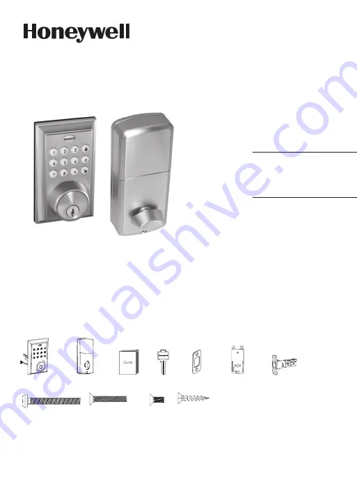
Package Includes:
1 - Exterior Faceplate
1 - Interior Faceplate
1 - User Guide
2 - Keys
1 - Strike Plate
1 - Mounting Plate
1 - Deadbolt Latch
1 - 1 3/8” Screws
2 - 5/16” Screws
2 - 1 “ Screws
5 - 3/4” Screws
Read this manual carefully before installing and operating!
Please carefully check the above list to confirm all items have been received. If any items are
missing, please contact Consumer Assistance. ( See page for contact information)
3/4” Screws
1” Screws
5/16” Screws
1 3/8” Screws
Mounting Plate
Deadbolt Latch
Exterior Faceplate
Interior Faceplate
User Guide
Keys
Strike plate
Summary of Contents for 8812309S
Page 25: ...23 BACK OF TEMPLATE ...