Honeywell 2MLF-HD2A User Manual Download Page 93

6. Global Constant and Global Variable 

6.2. Global Constant 

R200 

2MLF-HO2A, 2MLF-HD2A High Speed Counter Module User's Guide 

93 

May 2010 

Honeywell 

2.


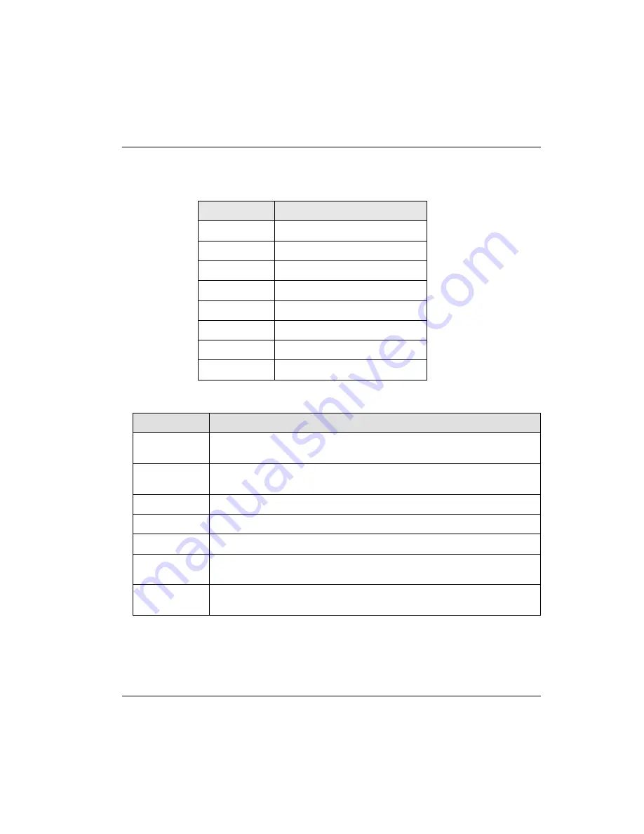
Pulse input types (channel 0: _Fxy_CH0_PLS_MODE, channel 1: 

_Fxy_CH1_PLS_MODE) 

Setting value 

Contents 

2 phase 1 multiplier 

2 phase 2 multiplier 

2 phase 4 multiplier 

CW/CCW 

1 phase /1 input /1 multiplier 

1 phase /1 input /2 multiplier 

1 phase /2 input /1 multiplier 

1 phase /2 input /2 multiplier 

3.


Comparison output types (channel 0: _Fxy_CH0_CP0 (1)_MODE, channel 1: 

_Fxy_CH1_CP0 (1)_MODE) 

Setting value 

Contents 

In case of current count value < comparison reference value, OUT0(1) is 

On 

In case of current count value ≤ comparison reference value, OUT0(1) is 

On 

In case of current count value = comparison reference value, OUT(1) is On 

In case of current count value ≥ comparison reference value, OUT(1) is On 

In case of current count value > comparison reference value, OUT(1) is On 

In case of comparison minimum value ≤ current count value ≤ comparison 

maximum value, OUT(1) is On 

In case of comparison minimum value ≥ current count value, current count 

value ≤ comparison maximum value, OUT(1) is On 

Summary of Contents for 2MLF-HD2A

Page 1: ...Honeywell Process Solutions 2MLF HO2A 2MLF HD2A High Speed Counter Module User s Guide 2MLF HO2A 2MLF HD2A R200 May 2010 Release 200 Honeywell ...

Page 2: ... and makes no express warranties except as may be stated in its written agreement with and for its customers In no event is Honeywell liable to anyone for any indirect special or consequential damages The information and specifications in this document are subject to change without notice Honeywell PlantScape Experion PKS and TotalPlant are registered trademarks of Honeywell International Inc Othe...

Page 3: ...ule used in association with CPU module of MasterLogic 200 PLC series hereinafter referred to as 2MLF H02A 2MLF HD2A Release Information Document Name Document ID Release Number Publication Date High Speed Counter Module User s Guide 2MLF HO2A 2MLF HD2A 200 May 2010 References The following list identifies all documents that may be sources of reference for material discussed in this publication Do...

Page 4: ...Garden Lane Phoenix AZ 85027 USA Europe Middle East and Africa EMEA Contact Phone Fascimile Mail Honeywell TAC EMEA 32 2 728 2345 32 2 728 2696 TAC BE02 Hermes Plaza Hermeslaan 1H B 1831 Diegem Belgium Pacific Contact Phone Fascimile Mail Email Honeywell Global TAC Pacific 1300 364 822 toll free within Australia 61 8 9362 9559 outside Australia 61 8 9362 9564 Honeywell Limited Australia 5 Kitchene...

Page 5: ...China 86 21 2219 6888 800 820 0237 400 820 0386 Honeywell China Co Ltd 33 F Tower A City Center 100 Zunyi Rd Shanghai 200051 People s Republic of China Global TAC China honeywell com Singapore Contact Phone Fascimile Mail Email Honeywell Global TAC South East Asia 65 6580 3500 65 6580 3501 65 6445 3033 Honeywell Private Limited Honeywell Building 17 Changi Business Park Central 1 Singapore 486073 ...

Page 6: ...an 81 3 6730 7160 81 3 6730 7228 Honeywell Japan Inc New Pier Takeshiba South Tower Building 20th Floor 1 16 1 Kaigan Minato ku Tokyo 105 0022 Japan Global TAC JapanJA25 honeywell com Elsewhere Call your nearest Honeywell office World Wide Web Honeywell Solution Support Online http www honeywell com ps Training Classes Honeywell Automation College http www automationcollege com ...

Page 7: ...AUTION Indicates a situation which if not avoided may result in equipment or work data on the system being damaged or lost or may result in the inability to properly operate the process CAUTION Indicates a potentially hazardous situation which if not avoided may result in minor or moderate injury It may also be used to alert against unsafe practices CAUTION symbol on the equipment refers the user ...

Page 8: ...ctive earth green or green yellow supply system conductor Functional earth terminal Used for non safety purposes such as noise immunity improvement NOTE This connection shall be bonded to Protective Earth at the source of supply in accordance with national local electrical code requirements Earth Ground Functional earth connection NOTE This connection shall be bonded to Protective Earth at the sou...

Page 9: ...s 25 2MLF HO2A HD2A 25 2 3 Specifications for Interface with External Devices 27 Arrangement of connector pins 27 Internal Circuit 30 2 4 Counter Functions 34 Pulse Input Mode 34 Counter Mode 40 Preset 44 Compared Output Mode 46 Carry Signal 50 Borrow Signal 50 Auxiliary Mode 50 3 INSTALLATION WIRING 57 Installation Environment 57 Handling Precautions 57 3 1 Wiring Precautions 58 Example of DC5V V...

Page 10: ...al Direct variables 75 Registering Special module variables 77 5 INTERNAL MEMORY I O SIGNALS 79 5 1 Internal memory configuration 79 Input setting area 79 Output Setting Area 81 Details Data Configuration 81 Status Display 84 5 2 I O Signals 85 Configuration of I O signals 85 6 GLOBAL CONSTANT AND GLOBAL VARIABLE 89 6 1 Overview 89 6 2 Global Constant 89 Configuration of Global Constant 89 Details...

Page 11: ...153 Carry borrow detection reset 154 Auxiliary mode setting and Enable auxiliary function 155 Sampling Count 157 Input Frequency Measure 159 Revolution Unit time 161 Counter Disable 163 Up down count selection 165 Use of external preset signal 165 Use of external auxiliary function signal 167 Type of comparison and comparison value setting 168 Enable comparison Enable comparison output Comparison ...

Page 12: ...ator 208 Increasing Counter 208 Decreasing Counter 208 Ring Counter 209 1 Phase Operation Mode 209 CW CCW Operation Mode 209 CW CCW Operation Mode 209 Preset 209 Gate 209 Compared Value 209 Carry 209 Borrow 210 LT Signal 211 EQ Signal 211 GT Signal 211 Section Signal or 211 External Preset 211 External Gate 211 9 2 Dimensions 212 9 3 GM Function Block Conversion Program 213 Preset value setting Fu...

Page 13: ...lication Operation Mode 35 Table 12 1 Phase 2 Input 1 Multiplication Operation Mode 36 Table 13 1 Phase 2 Input 2 Multiplication Operation Mode 37 Table 14 CW Clockwise CCW Counter Clockwise Operation Mode 40 Table 15 Counter Mode 40 Table 16 Compared Output Conditions 47 Table 17 Input Frequency Measure 54 Table 18 Input Setting Area 79 Table 19 Output Setting Area 81 Table 20 Count Type Setting ...

Page 14: ...atch 52 Figure 17 Sampling Count 53 Figure 18 Input Frequency Measure 54 Figure 19 Revolution Unit Time 55 Figure 20 Count Disable 56 Figure 21 Example of DC5V Voltage Output Wiring 59 Figure 22 Example of DC24V NPN Open Collector Output Wiring 60 Figure 23 Example of DC24V PNP Open Collector Output Wiring 61 Figure 24 Example of Line Driver Output Wiring 62 Figure 25 SoftMaster Icon 63 Figure 26 ...

Page 15: ...re 62 Example of Carry Borrow Resetting 125 Figure 63 Parameter Setting Screen for Auxiliary Mode1 125 Figure 64 Ladder Program for Auxiliary Mode Setting 126 Figure 65 Scan Program for Auxiliary Mode setting 127 Figure 66 Parameter Setting Screen 128 Figure 67 Ladder Program for Auxiliary Mode2 129 Figure 68 Scan Program for Auxiliary Mode Setting 2 130 Figure 69 Parameter Setting Screen for Samp...

Page 16: ...Figure 102 Scan program of 2MLI 2MLR series 160 Figure 103 Scan program of 2MLK series 161 Figure 104 Scan program of 2MLI 2MLR series 162 Figure 105 Scan program of 2MLK series 163 Figure 106 Scan program of 2MLI 2MLR series 164 Figure 107 Scan program of 2MLK series 165 Figure 108 Scan program of 2MLI 2MLR series 165 Figure 109 Scan program of 2MLK series 166 Figure 110 Scan program of 2MLI 2MLR...

Page 17: ...tion 189 Figure 135 Module Installation Information Setting Screen 190 Figure 136 I O Assigned Information Setting 191 Figure 137 I O Parameters Setting 192 Figure 138 Ladder Program 193 Figure 139 Ladder Program 194 Figure 140 RDY LED OFF 198 Figure 141 RDY LED Blinks 199 Figure 142 Counter Operation Error 201 Figure 143 Counter Value Error 202 Figure 144 Output Operation Error 203 Figure 145 Sys...

Page 18: ...Contents Figures xviii 2MLF HO2A 2MLF HD2A High Speed Counter Module User s Guide R200 Honeywell May 2010 ...

Page 19: ...e program Up Down counter function by means of the B phase input 2 If 2 phase is input then we can have 1 multiplier 2 multiplier 4 multiplier Up Down counter function by means of the difference in phase 3 If CW CCW is input Up Down counter function by means of A phase or B phase 4 Preset Gate function by applicable program or external input signal 5 At output contact of the built in transistor se...

Page 20: ...1 Introduction 1 2 Functions 20 2MLF HO2A 2MLF HD2A High Speed Counter Module User s Guide R200 Honeywell May 2010 ...

Page 21: ...unt input signal Signal A phase B phase Input Type Voltage Input Open Collector Differential Input Line Drive Signal Level DC 5 12 24V RS 422A Line Drive HTL LEVEL Line Drive Maximum coefficient speed 200kpps 500kpps HTL input is 250kpps Number of channels 2 Coefficient range Signed 32 bit 2 147 483 648 2 147 483 647 Count mode program setting Linear Count with Carry Borrow when 32 bit range is ex...

Page 22: ...ion program setting CW CCW 1 multiplication Control input Signal Preset instruction input auxiliary mode instruction input Signal Level DC 5V 12V 24V select terminal input type Signal type Voltage External output Output points 2 point channel for each channel terminal output available Type Select single compared or section compared output included or excluded program setting Output type Open colle...

Page 23: ...y internal external input during count operation Terminal 40 pin connector Internal current consumption 270mA 330mA Weight 90g ATTENTION In 2MLR system you can use HSC module only at extension base You cannot equip HSC module at basic base Pulse Input Specifications Table 2 Counter Input Specifications Item Specifications Voltage input type Different type Input voltage 24V DC 17 0V 26 4V 12V DC 9 ...

Page 24: ...5 5V Input current 3 6 mA 3 6 mA 3 6 mA ON guaranteed voltage 15 2 V 10 8V 4 1V OFF guaranteed voltage 3 2V 2 5V 1 4V ON delayed time Less than or equal to 1ms OFF delayed time Less than or equal to 1ms Transistor Output SINK Specifications Table 4 Transistor Output SINK Specifications Item Specifications Rated output DC 24V 100mA point Leaked current Less than or equal to 0 1mA Saturated area vol...

Page 25: ...2 Specifications 2 2 Designations of Parts R200 2MLF HO2A 2MLF HD2A High Speed Counter Module User s Guide 25 May 2010 Honeywell 2 2 Designations of Parts 2MLF HO2A HD2A Figure 1 Parts of 2MLF HO2A HD2A ...

Page 26: ...R200 Honeywell May 2010 Table 5 Parts and Functions No Designation Details 1 LED display A A phase pulse input B B phase pulse input P External preset input G External gate input OUT0 OUT0 compared output OUT1 OUT1 compared output READY RDY Ready signal 2 I O Connector Terminal for I O with external device ...

Page 27: ...yed in Table 6 Table 6 2MLF HO2A Connector Pin Arrangement Pin arrangement Pin No Designations of signals CH 0 CH 1 1 17 A12V A phase DC12V input 2 18 A24V A phase DC24V input 3 19 A_C A phase COM terminal 4 20 A5V A phase DC5V input 5 21 B12V B phase DC12V input 6 22 B24V B phase DC24V input 7 23 B_C B phase COM terminal 8 24 B5V B phase DC5V input 9 25 P12V Preset DC12V input 10 26 P24V Preset D...

Page 28: ...Guide R200 Honeywell May 2010 Pin arrangement Pin No Designations of signals CH 0 CH 1 14 30 G24V Gate DC24V input 15 31 G_C Gate COM terminal 16 32 G5V Gate DC5V input 33 35 OUT1 Compared output OUT1 34 36 OUT0 Compared output OUT0 37 38 24V Supply TERMINAL of external power DC24V 39 40 24G Supply TERMINAL of external power GND ...

Page 29: ...18 AI AI input LINE DRIVE TTL LEVEL input 3 19 AII AII input LINE DRIVE HTL LEVEL input 4 20 AII AII input LINE DRIVE HTL LEVEL input 5 21 BI BI input LINE DRIVE TTL LEVEL input 6 22 BI BI input LINE DRIVE TTL LEVEL input 7 23 BII BII input LINE DRIVE HTL LEVEL input 8 24 BII BII input LINE DRIVE HTL LEVEL input 9 25 P12V Preset DC12V input 10 26 P24V Preset DC24V input 11 27 P_C Preset COM termin...

Page 30: ...internal circuit of High Speed counters and external device is described in Table 8 1 2MLF HO2A Table 8 Internal Circuit of 2MLF HO2A I O Classific ation Internal circuit No Terminal Name Pin No Designation of signals CH 0 CH1 Input 1 A24V 2 18 A phase pulse input 24V 2 A12V 1 17 A phase pulse input 12V 3 A5V 4 20 A phase pulse input 5V 4 A_COM 3 19 A phase common 1 B24V 6 22 B phase pulse input 2...

Page 31: ...rcuit No Terminal Name Pin No Designation of signals CH 0 CH1 6 P12V 9 25 Preset input 12V 7 P5V 12 28 Preset input 5V 8 P_COM 11 27 Preset common 5 G24V 14 30 Gate input 24V 6 G12V 13 29 Gate input 12V 7 G5V 16 32 Gate input 5V 8 G_COM 15 31 Gate common Output 9 OUT0 34 32 External output 0 10 OUT1 33 35 External output 1 11 24V 37 38 External power 24V 12 24G 39 40 External power ground ...

Page 32: ...No Designation of signals CH 0 CH1 Input 1 AI 2 18 AI line driver input 2 AII 4 20 AII line driver input 3 AI 1 17 AI line driver input 4 AII 3 19 AII line driver input 1 BI 6 22 BI line driver input 2 BII 8 24 BII line driver input 3 BI 5 21 BI line driver input 4 BII 7 23 BII line driver input 5 P24V 10 26 Preset input 24V 6 P12V 9 25 Preset input 12V 7 P5V 12 28 Preset input 5V 8 P_COM 11 27 Pr...

Page 33: ...dule User s Guide 33 May 2010 Honeywell I O Classification Internal circuit No Terminal Name Pin No Designation of signals CH 0 CH1 7 G5V 16 32 Gate input 5V 8 G_COM 15 31 Gate common Output 9 OUT0 34 32 External output 0 10 OUT1 33 35 External output 1 11 24V 37 38 External power 24V 12 24G 39 40 External power ground ...

Page 34: ...t 4 The counter modules count in up count down count methods a For 1 phase input Up or Down count is achieved by program setting Up or Down count is achieved by B phase input signal b For 2 phase input Up or Down count is achieved by the setting difference in phase between A phase and B phase c For CW CCW input Up count is achieved if B phase is LOW as compared with A phase input Down count is ach...

Page 35: ... classification A Phase input pulse rising A Phase input pulse falling Up Down count setting signal OFF Up count Up Down count setting signal ON Down count Figure 2 Up Down Count Operation by Program Setting 1 phase 1 input 2 multiplication operation mode The counter counts A phase input pulses at the rising and falling edge The program setting or the up down count signal decides between up and do...

Page 36: ... the rising edge B phase input decides between up and down count operations Table 12 1 Phase 2 Input 1 Multiplication Operation Mode Up Down classification A Phase input pulse rising A Phase input pulse falling B phase input pulse OFF Up count B phase input pulse ON Down count Figure 4 Up Down Count Operation by B phase Input Signal 1 phase 2 input 2 multiplication operation mode The counter count...

Page 37: ... Count Operation by B Phase Input Signal 2 2 Phase Input Mode a 2 phase 1 multiplication operation mode The counter counts A phase pulse input at the rising edge If A phase input pulse precedes B phase input pulse up count operation starts at the rising edge of A phase pulse input If B phase input pulse precedes A phase input pulse down count operation starts at the falling edge of A phase pulse i...

Page 38: ...vely If A phase input precedes B phase input pulse up count operation starts at the rising and falling edge of A phase pulse input If B phase input precedes A phase input pulse down count operation starts at the rising and falling edge of A phase input pulse Up Down count classification A Phase input pulse rising A Phase input pulse falling A phase input pulse precedes B Up count Up count B phase ...

Page 39: ...ount classification A Phase input pulse rising A Phase input pulse falling A Phase input pulse rising A Phase input pulse falling A phase input pulse precedes B Up count Up count Up count Up count B phase input pulse precedes A Down count Down count Down count Down count Figure 8 2 Phase 4 Multiplication Operation Mode 2 CW Clockwise CCW Counter Clockwise operation mode The counter counts either a...

Page 40: ...F Down count Figure 9 CW Clockwise CCW Counter Clockwise Operation Mode Counter Mode Two types of counting modes can be selected for the specific application need Table 15 Counter Mode Classification 0H address for CH 0 19H address for CH 1 internal memory Linear Count Set to 0 Ring Count Set to 1 1 Linear Count mode a Linear Count range 2 147 483 648 2 147 483 647 b Up count If count value reache...

Page 41: ... 2MLF HD2A High Speed Counter Module User s Guide 41 May 2010 Honeywell c Down count If count value reaches the minimum value while decreasing Borrow occurs and count stops and decreasing is not available but increasing is available Figure 10 Linear Count ...

Page 42: ...um value c Ring Count Display If Ring Count user defined minimum value of Ring Count is displayed but the maximum value is not displayed as count d Ring Count Operation Up Count During up count mode if count value exceeds user defined maximum value Carry occurs and count is executed starting from minimum value Figure 11 Ring Count Down count During down count mode if count value reaches user defin...

Page 43: ... count If count reaches ring count maximum value it changes into ring count minimum value and carry occurs and count is executed until 2 147 483 647 If count exceeds 2 147 483 647 count is changed into 2 147 483 648 and executed repeatedly Figure 13 Ring Count based on Present Count Value During down count if count reaches minimum value borrow occurs and count is changed into ring count maximum va...

Page 44: ...lue is out of range then LED flickers and error occurs Use preset function or the like when using Ring Count to position the count value within the range LED is off and error disappears Preset 1 When Enable Preset is ON current count is changed into preset setting value Only with setting of preset current count is not changed and you have to execute the Enable Preset to change the current count 3 ...

Page 45: ... preset function by external input signal set Enable Preset as 1 ON turn on external preset input signal 2 If you execute the preset by external input signal external preset detection becomes 1 ON when external preset detection is 1 ON external preset is not executed In order to change external preset detection as 0 OFF turn on external preset detection reset ...

Page 46: ...put Mode 1 High Speed counter module has an output function used for comparing present count value with the compared value and hence generate an output 2 Two separate compared outputs are available for each channel 3 The seven output conditions are used for comparing present count value with compared value The conditions are shown below ...

Page 47: ...eases to be equal to or greater than compared value output is not sent out Count Value Compared Value If present count value is less than or equal to compared value output is sent out and if count value increases to be greater than compared value output is not sent out Count Value Compared Value If present count value is equal to compared value output is sent out and even if count value increases ...

Page 48: ...Compared Value If present count value is greater than or equal to compared value output is sent out and if count value decreases to be less than compared value output is not sent out Count Value Compared Value If present count value is greater than compared value output is sent out and if count value decreases to be less than or equal to compared value output is not sent out ...

Page 49: ...pared value s range output is not sent out Compared Value1 count Value count Value Compared Value2 If present count value is less than or equal to compared value 1 and greater than or equal to compared value 2 output is sent out and if count value increases decreases to exceed compared value s range output is not sent out 4 After compared output condition is set in order to make actual comparisons...

Page 50: ...ated can be cancelled by switching Carry Borrow Reset Signal ON Borrow Signal 1 Borrow signal occurs a When minimum value of the count range i e 2 147 483 648 is reached during Linear Count b When user defined minimum value of Ring Count is changed to the maximum value during Ring Count 6 Count status when Borrow signal occurs a Counting stops if Borrow occurs during Linear Count b Counting does n...

Page 51: ...unt Clear 1 When Auxiliary Mode Enabled Signal is ON present count value is set to 0 9 Setting method Set auxiliary setting mode to 1 and Auxiliary Mode Enabled Signal ON 10 Count clear function is used for clearing present count whenever Auxiliary Mode Enabled Signal is switched ON In other words while Auxiliary Mode Enabled Signal is ON count operation is not continuous Figure 15 Count Clear Cou...

Page 52: ...us 4 The latched count value is displayed until the next time Auxiliary Mode Enabled Signal is switched ON Figure 16 Count Latch Sampling Count When auxiliary mode enabled signal is ON it counts for a specified time Setting method Set auxiliary mode setting mode to 3 and set Time Setting and Auxiliary Mode Enabled signal ON Sampling Count Function is used to count from 0 for a specified time when ...

Page 53: ...de operation When both Auxiliary Mode Enabled Signal and the Auxiliary Mode in Progress Signal is ON at the same time Sampling Count function operates for a specified time Figure 17 Sampling Count Input Frequency Measure While Auxiliary Mode Enabled Signal is ON the counter measures the input frequency per second or set unit Setting method Set auxiliary mode setting mode to 4 and set Auxiliary Mod...

Page 54: ...ut mode is specified in Table 17 The update cycle and resolution is decided based on the applicable mode Table 17 Input Frequency Measure Frequency input mode value Basic unit Hz Updated cycle T ms 0 1 1000 1 10 100 2 100 10 3 1000 1 Display during auxiliary mode operation The input frequency measurement function operates with auxiliary mode operation when Auxiliary Mode Enabled Signal is ON Figur...

Page 55: ...umber of pulses for a specified time while Auxiliary Mode Enabled Signal is ON 14 Revolution Unit time can be derived using the following a The number of pulses updated for a specified time b The number of pulses per revolution input 15 The value of RPM is derived using the number of pulses per revolution input with the time duration set to 1 minute 60000ms 16 Display during auxiliary mode operati...

Page 56: ... 1 Count operation stops while Auxiliary Mode Enabled Signal is ON 2 Setting method Set auxiliary mode setting mode to 6 and set Time Setting and Auxiliary Mode Enabled Signal ON 3 Display during auxiliary mode operation While Auxiliary Mode Enabled Signal is ON count operation stops with auxiliary mode in progress Figure 20 Count Disable ...

Page 57: ...ature around 0 55 C Installation guidelines 1 Do not leave wire scraps inside the PLC while wiring or drilling screw holes 21 Do not install the system on a panel that also has a high voltage device installed on it 22 Keep a distance of at least 50mm from a duct or a near by module 23 Ground the system to an appropriate place that is free from noise Handling Precautions Please take following preca...

Page 58: ...se twisted pair shielded class 3 grounded wire 28 Keep the wiring away from power cable or I O line to avoid any inductive noise 29 Stabilized power must be used for filtering unwanted signal 30 Connect A phase only for 1 phase input Example of DC5V Voltage Output Wiring 1 If the pulse generator is of voltage output type example of wiring with HSC is shown in Figure 21 31 The wiring is identical i...

Page 59: ...3 Installation Wiring 3 1 Wiring Precautions R200 2MLF HO2A 2MLF HD2A High Speed Counter Module User s Guide 59 May 2010 Honeywell Figure 21 Example of DC5V Voltage Output Wiring ...

Page 60: ...er Module User s Guide R200 Honeywell May 2010 Example of DC12V NPN Open Collector Output Wiring This is the wiring example which it used the pulse generator Encoder or Manual pulse generator of NPN Open Collector output type Figure 22 Example of DC24V NPN Open Collector Output Wiring ...

Page 61: ...nter Module User s Guide 61 May 2010 Honeywell Example of DC24V PNP Open Collector output wiring This is the wiring example which it used the pulse generator Encoder or Manual pulse generator of PNP Open Collector output type Figure 23 Example of DC24V PNP Open Collector Output Wiring ...

Page 62: ...l May 2010 Example of Line Driver Output Wiring This is the wiring example which it used the pulse generator Encoder or Manual pulse generator of RS 422A Line Driver 5V level output type Figure 24 Example of Line Driver Output Wiring ATTENTION In case of 24V Level Line Driver you must connect to AII AII BII BII terminal ...

Page 63: ...eter setting of HS counter module The GUI offers convenience of usage to the user Execution of SoftMaster Figure 25 SoftMaster Icon 1 After SoftMaster is installed click SoftMaster shortcut icon on the desktop as shown in Figure 25 34 The initial screen of SoftMaster appears Parameters Setting and Monitoring 1 On the Project menu click New Project or click on the tool bar to display the screen as ...

Page 64: ...4 Operating Procedures and Monitoring 4 2 Operation Method 64 2MLF HO2A 2MLF HD2A High Speed Counter Module User s Guide R200 Honeywell May 2010 Figure 26 Project Window ...

Page 65: ...2A High Speed Counter Module User s Guide 65 May 2010 Honeywell 4 Once a project is created click Online Connection Settings or on the toolbar click to specify the connection method and connection stage and then click Settings to specify the communication port as shown in Figure 30 ...

Page 66: ...LF HO2A 2MLF HD2A High Speed Counter Module User s Guide R200 Honeywell May 2010 Figure 27 Setting Communication Ports 5 After all settings are completed click Online Connect or click on the tool bar Click Message Window Communication to check the connection status ...

Page 67: ...4 Operating Procedures and Monitoring 4 2 Operation Method R200 2MLF HO2A 2MLF HD2A High Speed Counter Module User s Guide 67 May 2010 Honeywell Figure 28 Connection Checking Screen ...

Page 68: ...rameters perform the following steps Step Action 1 On the Project Window double click I O parameters The I O parameters setting window is displayed as shown in Figure 29 Figure 29 I O Parameter Setting 2 Click module area of the applicable slot to select the applicable module 3 Double click the corresponding slot to specify the parameters or click Details to display the screen where parameters can...

Page 69: ... 4 3 Parameters Setting R200 2MLF HO2A 2MLF HD2A High Speed Counter Module User s Guide 69 May 2010 Honeywell Step Action Figure 30 Parameter Setting Window 1 4 On the parameters setting window set parameters as necessary for the operation ...

Page 70: ...etting 70 2MLF HO2A 2MLF HD2A High Speed Counter Module User s Guide R200 Honeywell May 2010 Step Action Figure 31 Parameter Setting Window 2 ATTENTION You must make the scan program to change parameter of the high speed counter module during CPU RUN mode ...

Page 71: ...itoring Test Monitoring Test screen To monitoring or testing perform the following steps Step Action 1 After connecting to PLC CPU through SoftMaster click Online Special Module Monitoring or click to display the screen as shown in Figure 32 Figure 32 Special Module Monitoring 2 On the module list dialog box current modules of PLC system are displayed ...

Page 72: ...he appropriate module and click Monitor menu to display the monitoring or test screen as shown in Figure 34 The monitoring or test screen is divided in upper and lower portions The upper portion displays monitoring item values of each special module In the lower portion parameter items of each module can be changed individually If you click Test button setting values is applied to current value ...

Page 73: ...TION 1 It is applied to only test operation to the parameter which changed by Test button If test operation is concluded the high speed counter module is operated by the parameter which was set by I O parameter or by the scan program 2 If PLC CPU module is STOP mode it is available to test operation and monitoring function However in case of RUN mode it is available only to monitoring function ...

Page 74: ...4 2MLF HO2A 2MLF HD2A High Speed Counter Module User s Guide R200 Honeywell May 2010 Step Action 4 To monitor the I O contact status click appropriate channel s flag monitoring area to display the monitoring screen Here contact status of each I O can be checked ...

Page 75: ... the variables for each special module These variables refer to the special module information that is set in the I O parameter Refer to section on I O Signals You can thereafter modify the variables and comments It is described the method to register automatically variables Global variables Constants of high speed counter module in SoftMaster Project of 2MLI series View Global Direct variables 1 ...

Page 76: ...4 Operating Procedures and Monitoring 4 5 Register Special Module Variables 76 2MLF HO2A 2MLF HD2A High Speed Counter Module User s Guide R200 Honeywell May 2010 Figure 35 View Variables ...

Page 77: ... 36 Variable Comment Window Registering Special module variables 1 Open the variable window to activate the menu to register special module variable 2 Select Edit Register Special Module variable to register special module variable First Global Direct Variables window has to be executed A message box appears as shown below Figure 37 Register Special Module Variable 1 ...

Page 78: ...ecial Module Variables 78 2MLF HO2A 2MLF HD2A High Speed Counter Module User s Guide R200 Honeywell May 2010 3 Click Yes to complete the Special Module variable registration that is set in I O parameter setting Figure 38 Register Special Module Variable 2 ...

Page 79: ...nternal memory and the data is described in this section Input setting area Table 18 Input Setting Area CH0 CH1 Details Data setting range Dec Hex Dec Hex 0 0H 25 19H Select counter type 0 or 1 1 1H 26 1AH Select pulse input type 0 7 2 2H 27 1BH Set preset value 2147483648 2147483648 3 3H 28 1CH 4 4H 29 1DH Ring count minimum value 2147483648 2147483648 5 5H 30 1EH 6 6H 31 1FH Ring count maximum v...

Page 80: ... single compared minimu m setting value section compared 2147483648 2147483648 15 FH 40 28H 16 10H 41 29H OUT1 compared based value maximum setting value section compared 2147483648 2147483648 17 11H 42 2AH 50 32H 50 32H Define output status when PLC CPU stops CH0 CH1 common 0 6 18 12H 43 2BH Select additional function type 0 60000 19 13H 44 2CH Section count time setting or Revolutions per hour c...

Page 81: ...lue UDa b 5 UDa b 10 Revolution per unit ATTENTION ab stands for the base and slot position on which High Speed Counter module is installed a implies base No b implies slot No Details Data Configuration 1 Counter type setting CH0 0H address CH1 9H address Table 20 Count Type Setting Setting value Dec Details 0 Linear count 1 Ring count 2 Pulse input type setting CH0 1H address CH1 1AH address Tabl...

Page 82: ...dition setting CH0 8H 9H address CH1 21H 22H address Table 22 Compared Condition Setting Classification Address Details CH 0 CH 1 OUT0 8H 21H Setting value Details 0 If present value compared value OUT is ON 1 If present value compared value OUT is ON 2 If present value compared value OUT is ON 3 If present value compared value OUT is ON 4 If present value compared value OUT is ON 5 If compared va...

Page 83: ...ction 5 Revolutions per hour function 6 Count prohibited function 5 Frequency displayed mode setting CH0 15H address CH1 2EH address Table 24 Frequency Displayed Mode Setting Setting value Dec Details 0 1 Hz unit displayed Unit frequency is updated for every 1000 ms 1 10 Hz unit displayed 100 ms unit frequency value updated 2 100 Hz unit displayed 10 ms unit frequency value updated 3 1000 Hz unit ...

Page 84: ...ywell May 2010 Status Display Bit 15 Bit 14 Bit 13 Bit 12 Bit 11 Bit 10 Bit 9 Bit 8 Bit 7 Bit 6 Bit 5 Bit 4 Bit 3 Bit 2 Bit 1 Bit 0 O Module Ready CH0 Error Flag CH0 Comparator Output01 CH0 Comparator Output0 CH0 Auxliary Function Flag CH0 Borrow CH0 Carry CH0 External Preset Command Flag CH0 Count Inc Dec Flag Figure 39 Status Display ...

Page 85: ...Variable Name Details UXa b 0 _ab_CH0 _DN CH0 Count Inc Dec Flag ON decreas ing OFF increasi ng UXa b 368 _ab_CH0_CN TEN CH0 Counter Enable Leve l Command UXa b 1 _ab_CH0 _EXTPR E CH0 External Preset Comma nd Flag UXa b 369 _ab_CH0_PR EEN CH0 Preset Enable Edg e Command UXa b 3 _ab_CH0 _CRY CH0 Carry UXa b 370 _ab_CH0_D WNCNT CH0 Inc Dec Count Setting Leve l Command UXa b 4 _ab_CH0 _BRW CH0 Borrow...

Page 86: ...tput UXa b 374 _ab_CH0_EQ 0RST CH0 Comp Output 0 EQUAL Reset Edge Command UXa b 14 _ab_CH0 _ERR CH0 error flag UXa b 375 _ab_CH0_EQ 1RST CH0 Comp Output 1 EQUAL Reset Edge Command UXa b 15 _ab_RDY Module Ready UXa b 378 _ab_CH0_CR YBRW CH0 Carry Borro w Reset Edge Command UXa b 16 _ab_CH1 _DN CH1 Count Inc Dec Flag ON decreas ing OFF increasi ng UXa b 379 _ab_CH0_EX TPST_EN CH0 External Preset Inp...

Page 87: ...UXING CH1 Auxliary Functio n Flag UXa b 385 _ab_CH1_PR EEN CH1 Preset Enable Edg e Command UXa b 22 _ab_CH1 _CMPOU T0 CH1 Compar ator Output0 Output UXa b 386 _ab_CH1_D WNCNT CH1 Inc Dec Count Setting Leve l Command UXa b 23 _ab_CH1 _CMPOU T1 CH1 Compar ator Output1 Output UXa b 387 _ab_CH1_AU XEN CH1 Auxiliary Function Enable Edg e Level command UXa b 30 _ab_CH1 _ERR CH1 Error Flag UXa b 388 _ab_...

Page 88: ...tails CH Signal Variable Name Details Reset Edge Command UXa b 391 _ab_CH1_EQ 1RST CH1 Comp Output 1 EQUAL Reset Edge Command UXa b 394 _ab_CH1_CR YBRW_RST CH1 Carry Borro w Reset Edge Command UXa b 395 _ab_CH1_EX TPST_EN CH1 External Preset Input Selection Command UXa b 396 _ab_CH1_EX TAUX_EN CH1 Aux Func Ext Input Selection Command UXa b 397 _ab_CH1_EX TPST_RST CH1 Ext Preset Detect Flag Reset C...

Page 89: ...ice 6 2 Global Constant CPU module of 2ML 2MLR series are sharing the global constant area for the data transmission and receiving It is PUT_ for the function block to transmit the data and GET_ for the receiving function block form 2MLI 2MLR CPU module to the global constant area of the high speed counter module About PUT_ GET_ function block please refer to section Programming Configuration of G...

Page 90: ...6 _Fxy_ CH1_R ING_M AX 31 Ring count maximum value 2147483648 2147483647 _Fxy_CH 0_CP0_M ODE 08 _Fxy_ CH1_C P0_M ODE 33 Select OUT0 comparison type _Fxy_CH 0_CP1_M ODE 09 _Fxy_ CH1_C P1_M ODE 34 Select OUT1 comparison type 0 6 _Fxy_CH 0_CP0_M IN 10 _Fxy_ CH1_C P0_MI N 35 OUT0 compared based value single compared minim um setting value section compared 0 6 _Fxy_CH 0_CP0_M AX 12 _Fxy_ CH1_C P0_MA X ...

Page 91: ...X_M ODE 43 Select additional function type 0 6 _Fxy_CH 0_PERIO D 19 _Fxy_ CH1_P ERIOD 44 Section count time setting or Revolutions per unit time setting 0 60000 _Fxy_CH 0_REV_U NIT 20 _Fxy_ CH1_R EV_UN IT 45 Revolutions per hour function pulses per revolution input 0 60000 _Fxy_CH 0_FREQ_ MODE 21 _Fxy_ CH1_F REQ_ MODE 46 Select frequency displayed mode 0 3 ATTENTION Fxy x means the base number and...

Page 92: ... setting range _Fxy_PLCSTOP_OUT_EN 50 When 2MLI CPU module is STOP mode comparison output status channel 0 channel 1 common 0 or 1 3 Output area of the error code Channel 0 Channel 1 Constant value Details Data setting range _Fxy_ERR_CODE 51 Error code channel 0 channel 1 common GET_ Details and Data Configuration 1 Count types channel 0 _Fxy_CH0_CNT_MODE channel 1 _Fxy_CH1_CNT_MODE Setting value ...

Page 93: ...t types channel 0 _Fxy_CH0_CP0 1 _MODE channel 1 _Fxy_CH1_CP0 1 _MODE Setting value Contents 0 In case of current count value comparison reference value OUT0 1 is On 1 In case of current count value comparison reference value OUT0 1 is On 2 In case of current count value comparison reference value OUT 1 is On 3 In case of current count value comparison reference value OUT 1 is On 4 In case of curr...

Page 94: ...lear 2 Count latch 3 Sampling count 4 Input frequency measure 5 Revolution measure per unit time 6 Count disable 5 The frequency display unit of input frequency measure channel 0 _Fxy_CH0_FREQ_MODE channel 1 _Fxy_CH1_FREQ_MODE Setting value Contents 0 1Hz 1 10Hz 2 100Hz 3 1000Hz 1kHz 6 The status of comparison output during operation mode of 2MLI CPU module is stop mode channel 0 channel 1 _Fxy_PL...

Page 95: ...ted It is double word dword to the data type of the range of output data 2 The display of operation status and the range of operation command CH Output CPU Module High speed counter Input CPU Module High speed counter Status Details Command Details CH 0 _xy_CH0_DN Count Up Down status _xy_CH0_CNTEN Count enable level _xy_CH0_EXTPRE Input detection of external preset _xy_CH0_PREEN Preset enable edg...

Page 96: ... selection edge _xy_CH0_EXTAUX _EN Selection of external additional function edge _xy_CH0_EXTPST _RST Detection reset of external preset edge CH 1 _xy_CH1_DN Count Up Down status _xy_CH1_CNTEN Count enable level _xy_CH1_EXTPRE Input detection of external preset _xy_CH1_PREEN Preset enable edge _xy_CH1_CRY Carry detection _xy_CH1_DWNCN T Up Down count selection level _xy_CH1_BRW Borrow detection _x...

Page 97: ...counter Input CPU Module High speed counter Status Details Command Details _xy_CH1_ERR Error detection _xy_CH1_EQ1RST Equal reset of comparison output 1 edge _xy_CH1_CRTBRW _RST Carry Borrow reset edge _xy_CH1_EXTPST _EN External preset selection edge _xy_CH1_EXTAUX _EN Selection of external additional function edge _xy_CH1_EXTPST _RST Detection reset of external preset edge ...

Page 98: ...6 Global Constant and Global Variable 6 3 Global Variable 98 2MLF HO2A 2MLF HD2A High Speed Counter Module User s Guide R200 Honeywell May 2010 ...

Page 99: ...mory This section describes the read write process of the internal memory 2MLK series of High Speed counter module at 2MLT CPU module Read Internal Memory Read Instruction is used for reading the details of High Speed counter module s internal memory to the PLC CPU The read data can be saved on PLC s CPU memory except F area 1 Operation of GET GETP Instruction GET Always executed with execution co...

Page 100: ...n Area Available n1 Slot No on which special module is installed Integer n2 Start address of special module s operation parameters setting area area to read the data from Integer n3 Start address of the device to save the read data M P K L T C D D n4 Number of words of the data to be read Integer a Setting Base and Slot Number Figure 41 Basic base ...

Page 101: ...odule User s Guide 101 May 2010 Honeywell Figure 42 Extension base stage 1 Figure 43 Extension base stage 2 3 Use of GET GETP instruction a HSC module is installed at slot 8 of basic base and While M00000 is ON it transmits the data data1 data2 of internal memory 5 and 6 to D00015 and D00016 ...

Page 102: ...ry Data D00015 5 Data1 D00016 6 Data2 b It transmits data at rising edge of M00000 c HSC module is installed at slot 4 of extension base stage 2 While M00001 is on it transmits data of internal memory 10 15 to D00001 D00006 2MLK CPU module HSC module D area Internal memory data D00001 10 Data 1 D00002 11 Data 2 D00003 12 data 3 D00004 13 Data 4 D00005 14 Data 5 D00006 15 Data 6 ...

Page 103: ... PUTP Instruction PUT Always executed with execution condition On Level PUTP Executed with execution condition of operation Start Edge 2 Configuration of PUT PUTP Instruction PUT Execution condition n1 n2 n3 n4 Figure 44 Configuration of PUT PUTP Instruction Type Description Area Available n1 Slot No on which special module is installed Integer n2 Start address of special module s internal memory ...

Page 104: ...7 Programming 7 2 Read Write Internal Memory 104 2MLF HO2A 2MLF HD2A High Speed Counter Module User s Guide R200 Honeywell May 2010 Figure 45 Basic base Figure 46 Extension base stage 1 ...

Page 105: ...M0000 is ON it transmits data of D00000 data1 to internal memory address 1 2MLK CPU module HSC module Data D area Internal memory Data1 D00000 1 PUT h000A 1 D00000 1 M00000 b It transmits data at the rising edge of M0000 c HSC module is equipped at slot 0 of extension base stage 1 While M00001 is on it transmits data D00001 D00006 to internal memory address 10 15 2MLK CPU module HSC module Data D ...

Page 106: ...7 Programming 7 2 Read Write Internal Memory 106 2MLF HO2A 2MLF HD2A High Speed Counter Module User s Guide R200 Honeywell May 2010 Data3 D00003 12 Data4 D00004 13 Data5 D00005 14 Data6 D00006 15 ...

Page 107: ...on Function block Classification Variable Description Input REQ Request execution BASE Base where HSC module is equipped SLOT Slot where HSC module is equipped MADDR Global constant area Output DONE Function Block execution status STAT Error information DATA Output data ATTENTION means that WORD DWORD INT UINT DINT UDINT type is available For REQ edge signal or level signal is available For MADDR ...

Page 108: ...NT INT Reads INT data from Global constant area MADDR GET_UINT UINT Reads UINT data from Global constant area MADDR GET_DINT DINT Reads DINT data from Global constant area MADDR GET_UDINT UDINT Reads UDINT data from Global constant area MADDR 2 Use of GET function block a HSC module is equipped at slot 8 of basic base While Read1 is on it transmits data of _F08_CH0_CNT_ MODE to Output data1 2MlI 2...

Page 109: ...e refer to SoftMaster user manual b It transmits data at the rising edge of execution condition c HSD module is equipped at slot 4 of extension base stage 2 While Read2 is on it transmits data of _F24_CH1_CP0 _MIN to OutputData2 XGI XGR CPU module HSC module Output variable DATA Input variable MADDR Global constant Constant value Data OutputData2 _F24_CH1_CP0_MIN 35 Data2 ...

Page 110: ...cription Input REQ Request execution BASE Base where HSC module is equipped SLOT Slot where HSC module is equipped MADDR Global constant area DATA Input data Output DONE Function block execution status STAT Error information ATTENTION means that WORD DWORD INT UINT DINT UDINT type is available For REQ edge signal or level signal is available For MADDR Global constant or integer is available Output...

Page 111: ... INT Writes INT data to Global constant area MADDR PUT_UINT UINT Writes UINT data to Global constant area MADDR PUT_DINT DINT Writes DINT data to Global constant area MADDR PUT_UDINT UDINT Writes UDINT data to Global constant area MADDR 2 Use of PUT function block a HSC module is equipped at slot 10 of basic base While Write1 is on it transmits data Data1 of InputData1 to _F0A_CH0_CNT_MODE 2MLI 2M...

Page 112: ... refer to SoftMaster user manual b It transmits data at the rising edge of execution condition c HSC module is equipped at slot 6 of extension base stage 1 While Write2 is on it transmits data Data2 of InputData2 to _F16_CH0_PRESET 2MLI 2MLR CPU module HSC module Data Input variable DATA Input variable MADDR Global constant Constant value Data2 Input data2 _F16_CH0_PRESET 2 ...

Page 113: ... U contact Operation through Program The PLC system configuration is displayed as shown below The High Speed counter module installed on slot 1 is referred to as 2MLF HD2A unless stated differently Figure 48 Operation through Program Count Type Setting through I O parameters Read write The default status for counter mode is Linear Count Ring Count is specified as shown in below I O Parameters Para...

Page 114: ...er s Guide R200 Honeywell May 2010 Figure 49 Parameter Setting Screen Figure 50 Scan Program Write the above parameters and then the scan program on the PLC Input A B phase The alternative method for parameter setting is the usage of Scan program using PUTP instructions as shown below ...

Page 115: ...Guide 115 May 2010 Honeywell Figure 51 Other Parameters Setting Method than I O Parameters Operation Mode Setting These are the following options for Operation Mode Setting The default mode is 2 phase 1 multiplication 2 phase 1 multiplication 2 phase 2 multiplication 2 phase 4 multiplication ...

Page 116: ... multiplication 1 phase 1 input 2 multiplication 1 phase 2 input 1 multiplication 1 phase 2 input 2 multiplication The following figure shows the parameter setting screen to write 2 phase 4 multiplication on the internal memory of High Speed counter module I O Parameters Module Register I O Parameters setting Figure 52 Parameter Setting Screen ...

Page 117: ...2A High Speed Counter Module User s Guide 117 May 2010 Honeywell Figure 53 Ladder Program Write the above parameters and ladder program on PLC The alternative method for parameter setting is the usage of Scan program using PUTP instructions as shown below ...

Page 118: ...7 Programming 7 4 Basic Program 118 2MLF HO2A 2MLF HD2A High Speed Counter Module User s Guide R200 Honeywell May 2010 Figure 54 Use of Scan Program to set I O parameters ...

Page 119: ...FF the counter does not operate Preset Setting 1 This can be achieved by first specifying the preset input value and then switching on Preset Enabled Signal 2 Since preset input value is a parameter value it can be set through I O Parameters Write See Figure 56 and through PUP PUTP instruction in the scan program See Figure 57 3 Since Preset Enabled Signal is set through I O instruction area the s...

Page 120: ...odule User s Guide R200 Honeywell May 2010 Figure 56 Preset value setting through Parameter Setting Screen Figure 57 Ladder Program to set the Preset Enabled Signal The alternative method for parameter setting is the usage of Scan program using PUTP instructions as shown below ...

Page 121: ...7 Programming 7 4 Basic Program R200 2MLF HO2A 2MLF HD2A High Speed Counter Module User s Guide 121 May 2010 Honeywell ...

Page 122: ... areas of D00200 and D00201 and present count value of CH1 U01 12 U01 13 is read onto the areas of D00300 and D00301 Setting of Compared Value and Compared Condition The following figure shows the example of compared condition 5 section compare included with the minimum compared value of 500 and the maximum compared value of 1000 Compared output is 0 respectively for the channel 0 and 1 Figure 61 ...

Page 123: ...7 Programming 7 4 Basic Program R200 2MLF HO2A 2MLF HD2A High Speed Counter Module User s Guide 123 May 2010 Honeywell Figure 59 Parameter Setting Screen Figure 60 Ladder Program ...

Page 124: ... 2MLF HD2A High Speed Counter Module User s Guide R200 Honeywell May 2010 The alternative method for parameter setting is the usage of Scan program using PUTP instructions as shown below Figure 61 Usage of Scan Program for Setting Compared Output ...

Page 125: ...setting program used during counter operation The Carry Borrow is reset or cleared by setting the specified bit of U address area Auxiliary Mode Setting 1 Count clear Figure 64 shows the example of setting Auxiliary Mode to 1 count clear through I O Parameters Figure 65 shows the example of the scan program with Auxiliary Mode set to 1 count clear and Auxiliary Mode operation enabled Figure 63 Par...

Page 126: ... 2010 Auxiliary Mode external input setting signal uses the signal input from external terminal gate input of High Speed counter to clear the counter Figure 64 Ladder Program for Auxiliary Mode Setting The alternative method for parameter setting is the usage of Scan program using PUTP instructions as shown below ...

Page 127: ... terminal gate input Even if both Auxiliary Mode external inputs setting signal U1 23 C and Auxiliary Mode Use instruction U1 23 3 is ON the counter is not cleared unless the external instruction is present 2 Count Latch Figure 67 shows the example of setting Auxiliary Mode to 2 Count Latch through I O Parameters Figure 68 shows an example of the scan program with Auxiliary Mode set to 2 Count Lat...

Page 128: ...7 Programming 7 4 Basic Program 128 2MLF HO2A 2MLF HD2A High Speed Counter Module User s Guide R200 Honeywell May 2010 Figure 66 Parameter Setting Screen ...

Page 129: ...2MLF HO2A 2MLF HD2A High Speed Counter Module User s Guide 129 May 2010 Honeywell Figure 67 Ladder Program for Auxiliary Mode2 The alternative method for parameter setting is the usage of Scan program using PUTP instructions as shown below ...

Page 130: ...igure 69 shows the example of setting Auxiliary Mode to 3 i e Sampling Count through I O parameters Section setting value for the sampling section is also set to 1000ms 1s respectively for channels 0 and 1 in this figure Figure 71 shows an example of the scan program with Auxiliary Mode set to 3 Sampling Count additional function operation enabled and then present section count value read ...

Page 131: ...amming 7 4 Basic Program R200 2MLF HO2A 2MLF HD2A High Speed Counter Module User s Guide 131 May 2010 Honeywell Figure 69 Parameter Setting Screen for Sampling Count Figure 70 Ladder Program for Sampling Count ...

Page 132: ...HO2A 2MLF HD2A High Speed Counter Module User s Guide R200 Honeywell May 2010 The alternative method for parameter setting is the usage of Scan program using PUTP instructions as shown below Figure 71 Scan Program for Auxiliary Mode Setting 3 ...

Page 133: ...requency Measure through I O Parameters Frequency mode unit is also set to 10Hz 100ms unit of frequency value updated respectively for the channels 0 and 1 as in the figure Figure 74 shows an example of the scan program with Auxiliary Mode set to 4 Input Frequency Measure Auxiliary Mode operation enabled and then present input frequency value read Figure 72 Parameter Setting Screen for Input Frequ...

Page 134: ...HO2A 2MLF HD2A High Speed Counter Module User s Guide R200 Honeywell May 2010 Figure 73 Ladder Program for Input Frequency Measure The alternative method for parameter setting is the usage of Scan program using PUTP instructions as shown below ...

Page 135: ...olution Unit Time Figure 75 shows the setting example of Auxiliary Mode to 5 revolutions per unit time through I O parameters Pulses per revolution can be also specified and the value is used for converting pulses per unit time to revolutions per unit time Section setting value can be also specified which the value per unit time is used for measuring revolutions per unit time ...

Page 136: ...ay 2010 Figure 75 Parameter Setting Screen for Revolution Unit Time Figure 76 Ladder Program for Revolution Unit Time The following figure shows an example of the scan program with Auxiliary Mode set to 5 Revolution Unit time Auxiliary Mode operation enabled and then present revolutions per unit time value read ...

Page 137: ... HD2A High Speed Counter Module User s Guide 137 May 2010 Honeywell Figure 77 Scan Program with Auxiliary Mode Set to 5 Revolution Unit time 6 Count Disable Figure 79 shows the example of setting Auxiliary Mode to 6 Count Disable through I O Parameters ...

Page 138: ...eed Counter Module User s Guide R200 Honeywell May 2010 Figure 79 shows an example of the scan program with Auxiliary Mode set to 6 Count Disable Auxiliary Mode operation enabled and then present count value read Figure 78 Parameter Setting Screen for Count Disable ...

Page 139: ...eed Counter Module User s Guide 139 May 2010 Honeywell Figure 79 Ladder Program for Count Disable The following figure shows the example of the scan program with Auxiliary Mode set to 6 Count Disable Auxiliary Mode operation enabled and then present count value read ...

Page 140: ...7 Programming 7 4 Basic Program 140 2MLF HO2A 2MLF HD2A High Speed Counter Module User s Guide R200 Honeywell May 2010 Figure 80 Count Disable Scan Program ...

Page 141: ...May 2010 Honeywell 7 5 Present Count Value Recovery in case of Power Failure This Scan program is used to recover the present count value in case of power failure by saving present count value in K area latch address and presetting the previous count value to the present count value Figure 81 Present Value Recovery in case of Power Failure ...

Page 142: ...ng to the following system HSC module is equipped at slot 1 of basic base 2 2MLR system is explained referring to the following system HSC module is equipped at slot of extension base 2MLP ACF 2MLK CPUH 2MLF H02A Figure 82 2MLK series system 2MLP ACF 2MLI CPUU 2MLF H02A Figure 83 2MLI series system 2MLR ACF 2MLR ACF 2MLR D8SF 2MLF H02A Figure 84 2MLR series system ...

Page 143: ...ing The following example explains how to set Ring Count Min and Max As for setting method by I O Parameter refer to Chapter 4 Setting content Parameter CH0 CH1 Count mode 1 Ring counter 1 Ring counter Ring counter min 0 0 Ring counter max 100000 100000 Program 1 Scan program of 2MLK series Figure 85 Scan program of 2MLK series ...

Page 144: ...7 Programming 7 6 Program 144 2MLF HO2A 2MLF HD2A High Speed Counter Module User s Guide R200 Honeywell May 2010 2 Scan program of2MLI 2MLR series Figure 86 Scan program of 2MLI 2MLR series ...

Page 145: ...eration become different with program example a If input contact point of function block is ON and execution of function block is compete DONE becomes 1 Namely front function block and back function block are not executed simultaneously and from left to right they are executed sequently b If input variable of function block is set incorrectly and error occurs DONE does not become 1 Namely if error...

Page 146: ... 2MLF HO2A 2MLF HD2A High Speed Counter Module User s Guide R200 Honeywell May 2010 For integer corresponding to global constant refer to Chapter 6 On the next program example scan program example using integer constant is omitted ...

Page 147: ...ule User s Guide 147 May 2010 Honeywell Pulse input mode setting The following program example shows the setting pulse input mode Setting contents Parameter CH0 CH1 Pulse input mode 3 CW CCW 3 CW CCW Program 1 Scan program of 2MLK series Figure 87 Scan program of 2MLK series ...

Page 148: ...7 Programming 7 6 Program 148 2MLF HO2A 2MLF HD2A High Speed Counter Module User s Guide R200 Honeywell May 2010 2 Scan program of 2MLI 2MLR series Figure 88 Scan program of 2MLI 2MLR series ...

Page 149: ...igh Speed Counter Module User s Guide 149 May 2010 Honeywell Counter check The following program example shows how to checking current counter and operation by auxiliary function Program 1 Scan program of 2MLK series Figure 89 Scan program of 2MLK series ...

Page 150: ... High Speed Counter Module User s Guide R200 Honeywell May 2010 2 Scan program of 2MLI 2MLR series Figure 90 Scan program of 2MLI 2MLR series ATTENTION In Scan program of 2MLI 2MLR the number of cell is changed by using icon or Change Columns of View ...

Page 151: ...uide 151 May 2010 Honeywell Preset value setting and enable preset The following program example explains about how to set preset value and enable preset Setting content Parameter CH0 CH1 Preset value 1000 1000 Program 1 Scan program of 2MLK series Figure 91 Scan program of 2MLK series ...

Page 152: ...7 Programming 7 6 Program 152 2MLF HO2A 2MLF HD2A High Speed Counter Module User s Guide R200 Honeywell May 2010 Figure 92 Scan program of 2MLI 2MLR series ...

Page 153: ...le User s Guide 153 May 2010 Honeywell Enable counter The following program example explains how to execute Enable counter Program 1 Scan program of 2MLK series Figure 93 Scan program of 2MLK series 2 Scan program of 2MLI 2MLR series Figure 94 Scan program of 2MLI 2MLR series ...

Page 154: ... R200 Honeywell May 2010 Carry borrow detection reset The following program example shows how to reset the detected carry borrow signal Program 1 Scan program of 2MLK series Figure 95 Scan program of 2MLK series 2 Scan program of 2MLI 2MLR series Figure 96 Scan program of 2MLI 2MLR series ...

Page 155: ...ample explains how to set auxiliary mode and executing Enable auxiliary function You can check the operation result of auxiliary function at Counter check Counter Clear When auxiliary function is ON change the current counter as 0 1 Setting contents Parameter CH0 CH1 Auxiliary mode 1 Counter Clear 1 Counter Clear 2 Program a Scan program of 2MLK series Figure 97 Scan program of 2MLK series ...

Page 156: ...7 Programming 7 6 Program 156 2MLF HO2A 2MLF HD2A High Speed Counter Module User s Guide R200 Honeywell May 2010 b Scan program of 2MLI 2MLR Figure 98 Scan program of 2MLI 2MLR series ...

Page 157: ...2010 Honeywell Sampling Count Counter from when Enable auxiliary is on to setting time is indicated at sampling counter Setting content Parameter CH0 CH1 Auxiliary mode 3 Sampling Count 3 Sampling Count Range value 5000 5000 Program 1 Scan program of 2MLK series Figure 99 Scan program of 2MLK series ...

Page 158: ...7 Programming 7 6 Program 158 2MLF HO2A 2MLF HD2A High Speed Counter Module User s Guide R200 Honeywell May 2010 2 Scan program of 2MLI 2MLR series Figure 100 Scan program of 2MLI 2MLR series ...

Page 159: ...le Enable auxiliary function is on input pulse is indicated at input frequency Unit of input frequency is depending on setting of Frequency Mode Setting content Parameter CH0 CH1 Auxiliary mode 4 Input Freq measure 4 Input Freq measure Frequency Mode 1 10Hz 1 10Hz Program 1 Scan program of 2MLK series Figure 101 Scan program of 2MLK series ...

Page 160: ...7 Programming 7 6 Program 160 2MLF HO2A 2MLF HD2A High Speed Counter Module User s Guide R200 Honeywell May 2010 2 Scan program of 2MLI 2MLR series Figure 102 Scan program of 2MLI 2MLR series ...

Page 161: ...se is calculated and indicated at revolution unit time For revolution unit time Range value and Pulse Rev value should be set Setting contents Parameter CH0 CH1 Auxiliary mode 5 Revolution Unit time 5 Revolution Unit time Range value 1000 1000 Pulse Rev value 200 200 Program 1 Scan program of 2MLK series Figure 103 Scan program of 2MLK series 2 Scan program of 2MLI 2MLR series ...

Page 162: ...7 Programming 7 6 Program 162 2MLF HO2A 2MLF HD2A High Speed Counter Module User s Guide R200 Honeywell May 2010 Figure 104 Scan program of 2MLI 2MLR series ...

Page 163: ...Module User s Guide 163 May 2010 Honeywell Counter Disable While Enable auxiliary is on counting is not executed Setting contents Parameter CH0 CH1 Auxiliary mode 6 Count Disable 6 Count Disable Program 1 Scan program of 2MLK series Figure 105 Scan program of 2MLK series ...

Page 164: ...7 Programming 7 6 Program 164 2MLF HO2A 2MLF HD2A High Speed Counter Module User s Guide R200 Honeywell May 2010 2 Scan program of 2MLI 2MLR series Figure 106 Scan program of 2MLI 2MLR series ...

Page 165: ... set as 1 phase 1 input 1 mutiplication 2 multiplication Program 1 Scan program of 2MLK series Figure 107 Scan program of 2MLK series 2 Scan program of 2MLI 2MLR series Figure 108 Scan program of 2MLI 2MLR series Use of external preset signal The following program examples allows you to Enable preset by external preset signal and executing reset when external preset signal is detected Program 1 Sc...

Page 166: ...7 6 Program 166 2MLF HO2A 2MLF HD2A High Speed Counter Module User s Guide R200 Honeywell May 2010 Figure 109 Scan program of 2MLK series 2 Scan program of 2MLI 2MLR series Figure 110 Scan program of 2MLI 2MLR series ...

Page 167: ...well Use of external auxiliary function signal The following program example allows you to Enable auxiliary function by external auxiliary function signal Program 1 Scan program of 2MLK series Figure 111 Scan program of 2MLK series 2 Scan program of 2MLI 2MLR series Figure 112 Scan program of 2MLI 2MLR series ...

Page 168: ...rison value setting The following program example explains type of comparison and comparison value setting Setting content Parameter CH0 CH1 Comp output 0 Comp output 1 Comp output 0 Comp output 1 Comp output mode 1 5 1 5 Comp output min 10 150 10 150 Comp output max 150 No meaning 300 150 No meaning 300 Program 1 Scan program of 2MLK series ...

Page 169: ...7 Programming 7 6 Program R200 2MLF HO2A 2MLF HD2A High Speed Counter Module User s Guide 169 May 2010 Honeywell Figure 113 Scan program of 2MLK series 2 Scan program of 2MLI 2MLR series ...

Page 170: ...7 Programming 7 6 Program 170 2MLF HO2A 2MLF HD2A High Speed Counter Module User s Guide R200 Honeywell May 2010 Figure 114 Scan program of 2MLI 2MLR series ...

Page 171: ...71 May 2010 Honeywell Enable comparison Enable comparison output Comparison agreement reset The following program example explains how to execute Enable comparison Enable comparison output Comparison agreement reset Program 1 Scan program of 2MLK series Figure 115 Scan program of 2MLK series ...

Page 172: ...7 Programming 7 6 Program 172 2MLF HO2A 2MLF HD2A High Speed Counter Module User s Guide R200 Honeywell May 2010 2 Scan program of 2MLI 2MLR series Figure 116 Scan program of 2MLI 2MLR series ...

Page 173: ... The following program example explains how to set status of comparison output when 2MLT 2MLK 2MLI 2MLR CPU module is STOP Setting content Parameter CH0 CH1 Comparison output status when XGT CPU module is STOP 1 Hold comparison output Program 1 Scan program of 2MLK series Figure 117 Scan program of 2MLK series 2 Scan program of 2MLI 2MLR series ...

Page 174: ...s Guide R200 Honeywell May 2010 Figure 118 Scan program of 2MLI 2MLR series Error status and error code The following program example explains how to check error status and error code occurred at HSC module Program 1 Scan program of 2MLK series Figure 119 Scan program of 2MLK series ...

Page 175: ...of 2MLI 2MLR Figure 120 Scan program of 2MLI 2MLR series Hold count when power fails The following program example explains how to hold current count To prepare when PLC power is off current count is saved every scan and if PLC power restart preset operation is executed with the saved count Program 1 Scan program of 2MLK series ...

Page 176: ...7 6 Program 176 2MLF HO2A 2MLF HD2A High Speed Counter Module User s Guide R200 Honeywell May 2010 Figure 121 Scan program of 2MLK series 2 Scan program of 2MLI 2MLR series Figure 122 Scan program of 2MLI 2MLR series ...

Page 177: ...sed for safe operation of Preset value setting and preset allowance 2 In scan program of 2MLI 2MLR series to hold data of CH0 current count and CH1 current count when PLC power is off the following setting is necessary a On Basic Parameter set Restart Method as Warm Restart b On scan program set CH0 current count and CH1 current count as Retain variable ...

Page 178: ...7 Programming 7 6 Program 178 2MLF HO2A 2MLF HD2A High Speed Counter Module User s Guide R200 Honeywell May 2010 ...

Page 179: ...ar This motor rotates with the start signal effectively moving the object car High Speed Counter then counts the pulses from the encoder installed on the motor The pulse count is used to derive the distance moved and to stop the object car at the 1st stop position When the 1st Work Complete Signal is ON the motor then moves the object car to the 2nd stop position and stops When the 2nd Work Comple...

Page 180: ...art instruction P001 1st work complete signal P002 2nd work complete signal Output P010 Motor forward rotation signal ON Forward rotation OFF Stop P011 Motor reverse rotation signal ON Reverse rotation OFF Stop P020 P02F High Speed counter present value displayed BCD Operation type Figure 125 Operation Type 1 The difference of 100 between stop position and decelerated position is the delayed stop ...

Page 181: ...7 Programming 7 7 Application Program R200 2MLF HO2A 2MLF HD2A High Speed Counter Module User s Guide 181 May 2010 Honeywell Operation timing Figure 126 Operation Timing ...

Page 182: ...LF HO2A 2MLF HD2A High Speed Counter Module User s Guide R200 Honeywell May 2010 Program through I O Parameter Setting 1 Module installation information setting Figure 127 Module Installation Information Setting 2 I O assigned information setting ...

Page 183: ...F HD2A High Speed Counter Module User s Guide 183 May 2010 Honeywell Figure 128 I O Assigned Information Setting I O slot fixed points assigned 1 slot 64 points I O slot changeable points assigned Changeable based on module installed 3 I O parameters setting ...

Page 184: ...7 Programming 7 7 Application Program 184 2MLF HO2A 2MLF HD2A High Speed Counter Module User s Guide R200 Honeywell May 2010 Figure 129 I O Parameters Setting ...

Page 185: ...7 Programming 7 7 Application Program R200 2MLF HO2A 2MLF HD2A High Speed Counter Module User s Guide 185 May 2010 Honeywell Figure 130 Ladder Program for object car control ...

Page 186: ...7 Programming 7 7 Application Program 186 2MLF HO2A 2MLF HD2A High Speed Counter Module User s Guide R200 Honeywell May 2010 4 Program through PUT GET Figure 131 Ladder Program ...

Page 187: ...7 Programming 7 7 Application Program R200 2MLF HO2A 2MLF HD2A High Speed Counter Module User s Guide 187 May 2010 Honeywell Figure 132 Ladder Program contd ...

Page 188: ...olution angle setting OUT0 means High Speed counter terminal output Start switch Drilling complete sign Transmission 2MLP ACF1 2MLK CPU 2MLI D22A 2MLI D22A 2MLF HO2A 2MLQ TR2A P30 P31 Output P010 P01F P000 M OUT0 GM P001 Figure 133 System Configuration Operational Details If the start switch is pressed drilling stops after rotation up to the specified degree 60 If Drilling Complete signal is ON dr...

Page 189: ...7 Programming 7 7 Application Program R200 2MLF HO2A 2MLF HD2A High Speed Counter Module User s Guide 189 May 2010 Honeywell Operation Diagram Figure 134 Operation Diagram of 1 Revolution ...

Page 190: ...rogram 190 2MLF HO2A 2MLF HD2A High Speed Counter Module User s Guide R200 Honeywell May 2010 Program through I O Parameters setting 1 Module installation information setting Figure 135 Module Installation Information Setting Screen ...

Page 191: ...A High Speed Counter Module User s Guide 191 May 2010 Honeywell 2 I O assigned information setting Figure 136 I O Assigned Information Setting I O slot fixed points assigned 1 slot 64 points I O slot changeable points assigned Changeable based on module installed ...

Page 192: ...eed Counter Module User s Guide R200 Honeywell May 2010 3 I O parameters setting Figure 137 I O Parameters Setting Compared output 0 minimum output value 1 000 Pulses 1 revolution 360 So the number of pulses for 60 rotation is X 60 1000 360 166 Pulses when rotated 60 166 ...

Page 193: ...7 Programming 7 7 Application Program R200 2MLF HO2A 2MLF HD2A High Speed Counter Module User s Guide 193 May 2010 Honeywell Figure 138 Ladder Program ...

Page 194: ...7 Programming 7 7 Application Program 194 2MLF HO2A 2MLF HD2A High Speed Counter Module User s Guide R200 Honeywell May 2010 4 Program through PUT GET Figure 139 Ladder Program ...

Page 195: ...r error 20 120 Counter type range exceeded Blinks every 1 sec 21 121 Pulse input type range exceeded 22 122 Auxiliary Mode type range exceeded 23 123 Sampling Count value range exceeded 24 124 Compared output0 type range exceeded 25 125 Compared output1 type range exceeded 26 126 Preset value exceeded counter range 27 127 Ring counter minimum value Ring counter maximum value input 28 128 Compared ...

Page 196: ...e module status is normal RUN LED is ON If two or more errors occur the module saves the first error code generated The displayed error is deleted first and then the next error is displayed In case of fatal error where LED blinks every 0 2 sec recycle the power OFF ON to delete the error In case of non fatal error where LED blinks every 1 sec the error can be removed without recycling the power OF...

Page 197: ...blinks See Figure 142 Counter status of HS counter module The counter value is the same as before See Counter Operation Error under Troubleshooting sequence See Figure 143 Output status of HS counter module The change of counter value is not consistent with operation status See Counter Value Error under Troubleshooting sequence See Figure 144 Output operation is not available See Figure 145 Output...

Page 198: ...8 Troubleshooting 8 3 Troubleshooting Sequence 198 2MLF HO2A 2MLF HD2A High Speed Counter Module User s Guide R200 Honeywell May 2010 8 3 Troubleshooting Sequence RDY LED OFF Figure 140 RDY LED OFF ...

Page 199: ...Y LED Blinks Figure 141 RDY LED Blinks Table 29 Detailed Remedies for Operation Parameter Errors Error code Dec Description Action CH0 CH1 20 120 Counter type range exceeded Set counter type to 0 7 21 121 Pulse input type range exceeded Set pulse input type to 0 1 22 122 Auxiliary Mode type range exceeded Set Auxiliary Mode type to 0 6 ...

Page 200: ...inimum value exceeded maximum input range Set compared output0 minimum Value maximum value within counter range 29 129 Compared output0 maximum value exceeded maximum input range 30 130 Compared output 0 minimum Value compared output 0 maximum value set Set to compared output0 minimum value maximum value range 31 131 Compared output1 minimum value exceeded maximum input range Set compared output1 ...

Page 201: ...8 Troubleshooting 8 3 Troubleshooting Sequence R200 2MLF HO2A 2MLF HD2A High Speed Counter Module User s Guide 201 May 2010 Honeywell Counter Operation Error Figure 142 Counter Operation Error ...

Page 202: ...8 Troubleshooting 8 3 Troubleshooting Sequence 202 2MLF HO2A 2MLF HD2A High Speed Counter Module User s Guide R200 Honeywell May 2010 Counter Value Error Figure 143 Counter Value Error ...

Page 203: ...8 Troubleshooting 8 3 Troubleshooting Sequence R200 2MLF HO2A 2MLF HD2A High Speed Counter Module User s Guide 203 May 2010 Honeywell Output Operation Error Figure 144 Output Operation Error ...

Page 204: ... HSC module Execution Sequence The following two options are used for the execution sequence 1 Select Monitor System Monitoring and on the module screen click right mouse button to display Module Information 2 Select Monitor System Monitoring and double click module screen Module Information 1 Module Information shows information of the current module 2 OS version shows the O S version information...

Page 205: ...8 Troubleshooting 8 3 Troubleshooting Sequence R200 2MLF HO2A 2MLF HD2A High Speed Counter Module User s Guide 205 May 2010 Honeywell System Monitoring Figure 145 System Monitoring ...

Page 206: ...8 Troubleshooting 8 3 Troubleshooting Sequence 206 2MLF HO2A 2MLF HD2A High Speed Counter Module User s Guide R200 Honeywell May 2010 ...

Page 207: ...ion Its basic principle is if infrared rays from LED pass the slit disk and reaches the light receiving element analog electric sign is output which is converted by voltage comparator to digital sign to be output Figure 147 Encoder Encoder output is classified into 3 types A phase A or B phase and A or B or Z phase 1 A phase Basic output signal of pulses is output as many as the number of resoluti...

Page 208: ...s If rotated in clockwise direction forward pulses are generated and if rotated in anticlockwise direction reverse pulses are generated Increasing Counter The counter value increases from 2 147 483 648 to 2 147 483 647 for 32 bit counter Figure 148 Increasing Counter Decreasing Counter The counter value decreases from 2 147 483 647 to 2 147 483 648 for 32 bit counter Figure 149 Decreasing Encounte...

Page 209: ... input pulse CW CCW Operation Mode Mode used to count direction of the pulse CW CCW Operation Mode Mode used to count 2 phase input pulse Preset Mode used to set present counter value to discretionary value Gate Signal used to enable additional function operation Compared Value Basic value used for comparing counter value in size Carry Signal generated when Linear count changes from 2 147 483 646 ...

Page 210: ... Module User s Guide R200 Honeywell May 2010 Figure 151 Carry Borrow Signal generated when Linear count changes from 2 147 483 648 to 2 147 483 647 and when Ring count changes from the minimum value to the maximum value during decreasing count operation Figure 152 Borrow ...

Page 211: ...if present counter value compared value GT Signal Signal displayed if present counter value compared value Section Signal or Signal displayed if present counter value is between two user defined values or exceeds the two values External Preset External signal used to change present counter value to discretionarily specified value External Gate External signal used to enable the additional function...

Page 212: ...9 Appendix 9 2 Dimensions 212 2MLF HO2A 2MLF HD2A High Speed Counter Module User s Guide R200 Honeywell May 2010 9 2 Dimensions 2MLF HO2A HD2A Unit mm 0 2 0 0 2 0 27 98 Figure 153 Dimensions 98 ...

Page 213: ... edge BASE USINT Base Number Base number where HSC module is equipped SLOT USINT Slot Number Slot number where HSC module is equipped CH BOOL Chann el Ch0 0 Ch1 1 PSET _VAL DINT Preset range 2 147 483 648 2 147 483 647 Output DONE BOOL Execution status If it completes it outputs 1 and holds If error occurs it outputs 0 STAT USINT Error status In case of error outputs error code Preset value settin...

Page 214: ... 02 at MADDR result of 2MLI 2MLR FB is same 2 If you use PUT_DINT instead of PUT_DWORD preset action is same At this time data type of input variable DATA becomes DINT 3 Not Preset value setting FB HSCC_PRE but also Mode setting function HSCC_NOD Auxiliary function setting function HSCC_AUX Comparison setting function HSCC_CMP Count read function HSCC_CNT Operation information setting function HSC...

Page 215: ...e setting function block sets pulse input type and count type of HSC module Function Block type Classifi cation Variable name Type Contents Input REQ BOOL FB execution Executed when changing 0 1 Rising edge BASE USINT Base Number Base number where HSC module is equipped SLOT USINT Slot Number Slot number where HSC module is equipped CH BOOL Chann el Ch0 0 Ch1 1 CNT_ MODE BOOL Count type 0 Linear c...

Page 216: ...n input 6 1phase 2input 1multiplication B phase up down input 7 1phase 2input 2multiplication B phase up down input RING_MIN DINT Ring upper limit 2 147 483 648 2 147 483 647 RING_MAX DINT Ring lower limit 2 147 483 648 2 147 483 647 Output DONE BOOL Execution status If it completes it outputs 1 and holds If error occurs it outputs 0 STAT USINT Error status In case of error outputs error code 2 Mo...

Page 217: ...ODE 00 Ch1 _Fxy_CH1_CNT_MODE 25 DATA DWOR D Count type setting 0 Linear count 1 Ring count Output DONE BOOL Execution status If it completes it outputs 1 and holds If error occurs it outputs 0 STAT USINT Error status In case of error outputs error code b Pulse input type setting Function Block Type Classifica tion Variabl e name Type Contents Input REQ BOOL FB execution Executed when changing 0 1 ...

Page 218: ...put 7 1phase 2input 2multiplication B phase up down input Output DONE BOOL Execution status If it completes it outputs 1 and holds If error occurs it outputs 0 STAT USINT Error status In case of error outputs error code c Ring count lower limit setting Function Block type Classific ation Variable name Type Contents Input REQ BOOL FB execution Executed when changing 0 1 Rising edge BASE USINT Base ...

Page 219: ... Block type Classificat ion Variable name Type Contents Input REQ BOOL FB execution Executed when changing 0 1 Rising edge BASE USINT Base Number Base number where HSC module is equipped SLOT USINT Slot Number Slot number where HSC module is equipped MADDR UINT Channel Ch0 _Fxy_CH0_RING_MAX 06 Ch1 _Fxy_CH0_RING_MAX 31 DATA DWORD Ring count upper limit 2 147 483 648 2 147 483 647 Output DONE BOOL E...

Page 220: ...9 Appendix 9 3 GM Function Block Conversion Program 220 2MLF HO2A 2MLF HD2A High Speed Counter Module User s Guide R200 Honeywell May 2010 ...

Page 221: ...9 Appendix 9 3 GM Function Block Conversion Program 221 2MLF HO2A 2MLF HD2A High Speed Counter Module User s Guide R200 Honeywell May 2010 ...

Page 222: ...Honeywell Process Solutions 1860 W Rose Garden Lane Phoenix AZ 85027 USA ...

Reviews: