


Power up tests
Connecting the battery will not
power up the panel, power up will
occur after mains is applied.
The total system should be tested
in accordance with the
commissioning requirements of
BS5839:Part 1:2002 + A2:2008 or
other standard specified by the
system purchaser.
NOTE:
The commissioning
procedures assume that the
system has been installed as
per instructions in this booklet.
Checks before power up
q
Ensure you have 'as fitted
drawings'
q
check the system has been
installed to the project
requirements.
q
if necessary, action the installer
to carry out rectification work.
q
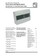
Remove the EEPROM
protection link from connector
P8, see Figure 14.
Initial power up
a) Disconnect cables to terminals
of zone, sounder, class
change, auxiliary, common fire
and fault circuits. Ensure each
cable is marked for
reconnection to respective
terminals later.
b) Connect end-of-line capacitor
units to zones and end-of-line
resistor units to sounder
circuits for initial power up.
c) Check mains connection and
switch on the mains power to
the control panel.
d) Now connect the battery
supply, see
Figure 14.
e) Check the panel provides a
normal healthy indication, with
the green light lit.
Zone circuit tests
a) Transfer the end-of-line
capacitor unit to the last device
(detector or manual call point)
on a zone circuit.
b) Connect the zone cable to the
zone circuit terminals.
c) Carry out zone open circuit and
short circuit tests and check
appropriate indications are
given.
d) Repeat the above for other
zone circuits.
Sounder circuit tests
a) Transfer the end-of-line
resistor unit to the last device
on a sounder circuit.
b) Connect the sounder circuit
cable to the sounder circuit
terminals.
c) Carry out sounder open and
short circuit tests and check
appropriate indications are
given.
d) Repeat the above for other
sounder circuits.
EEPROM Protection link
NOTE:
Ensure that at the end
of Commissioning and System
tests the EEPROM protection
link is fitted to connector P8,
see Figure 14.
Fire Panels
Power up tests
4188-424 issue 4_Part 1_10-09
10
+
-
Control panel
NOTE: A label is supplied in the spares pack
which can be located on this cover to identify
zone location
Connection for 12V 2.1Ah Batteries
For 1, 2 and 4 zone repeat panel
a) Open the
lower outer cover
b) Remove the
lower inner plate
Instru Zone designation
c) Fit the batteries and
connect the battery cables
+
-
Connection for 12V 3.4Ah Batteries
For 8 zone panels
+
-
+
-
Zones
FIRE
Faults
System
Power
Earth
Sounder
Disabled
Sound
Alarms
Silence
Alarms
1
2
3
4
5
6
7
8
9
0
v
Test
Access /
Function
1
2
3
4
5
6
7
8
Cancel
Buzzer
Reset
System
Power
Shift
Display
Day/Night
1
8
P8
EEPROM
Protection
fitted across
pins 1 and 2
Figure 14 Battery installation and EEPROM protection link