background image


Page 2 of 5 


62-86-33-41 

Table 1  1000 Ohm Installation Procedure 

Step Action 

Remove covers 

Remove all 3 covers (top and both rear covers) 

Remove potentiometer 

Disconnect potentiometer wires at the terminal board.  (Terminals 32, 33, 34, 35, 36 and 37. ) 

Disconnect potentiometer from mounting plate. Save the nuts for next step. 

Mount the new potentiometer using saved nuts. 


Slide the potentiometer actuator sleeve through the potentiometer and over the end of the cam bushing.  
Push the sleeve in potentiometer fitting the pin into the slot of the potentiometer.   

Summary of Contents for 10260A Series

Page 1: ...d To perform the installation procedure you will need the following tools Medium Flat blade screwdriver Medium Phillips screwdriver Small needle nosed pliers Procedure WARNING Disconnect power before accessing components inside the actuator Failure to do so may result in death or serious injury ATTENTION When working with Printed Wiring Assemblies PWAs always protect against electrostatic discharg...

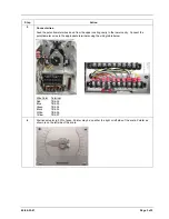
Page 2: ...ntiometer wires at the terminal board Terminals 32 33 34 35 36 and 37 Disconnect potentiometer from mounting plate Save the nuts for next step 3 Mount the new potentiometer using saved nuts 4 Slide the potentiometer actuator sleeve through the potentiometer and over the end of the cam bushing Push the sleeve in potentiometer fitting the pin into the slot of the potentiometer ...

Page 3: ...ity Connect the potentiometer wires to the appropriate terminals using the wiring table below Wire Color Terminal Red TB4 32 Blue TB4 33 Green TB4 34 Black TB4 35 White TB4 36 Yellow TB4 37 6 Position actuator to 50 of span Pointer may be on either the right or left side of the scale Pointer as shown is on the left side of the scale ...

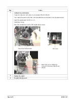
Page 4: ...s Ω to terminals TB4 35 TB4 36 Use a small allen wrench in the hole on the potentiometer actuator sleeve to turn the potentiometer Adjust the potentiometer to 500 Ω 5 Ω Install the set screw When the potentiometer is set for 500 Ω tighten the set screw 8 Replace the gasket 9 Re attach the top cover ...

Page 5: ...ell will repair or replace without charge those items it finds defective The foregoing is Buyer s sole remedy and is in lieu of all other warranties expressed or implied including those of merchantability and fitness for a particular purpose Specifications may change without notice The information we supply is believed to be accurate and reliable as of this printing However we assume no responsibi...

Reviews: