


11-15
dummyhead
dummyhead
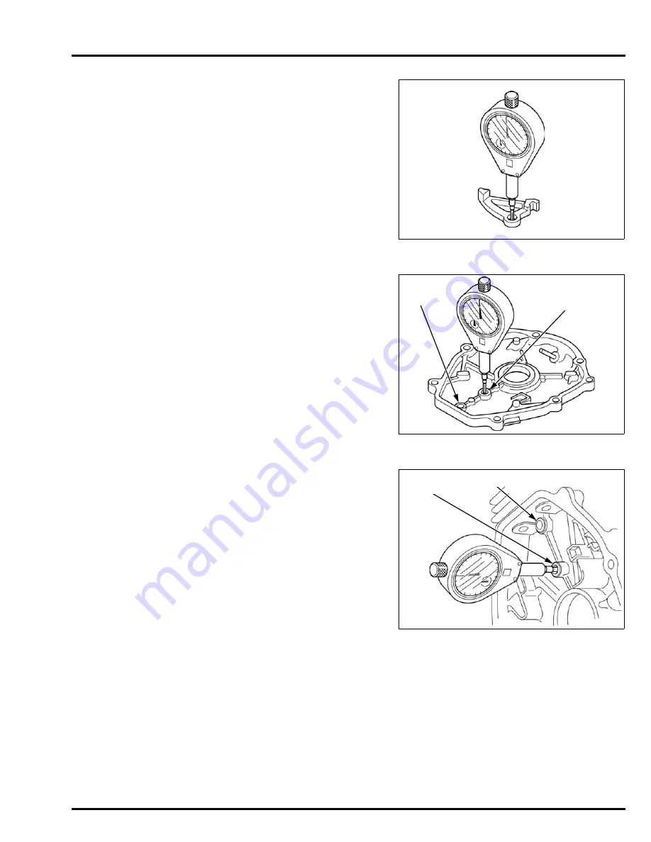
CRANKCASE
VALVE LIFTER I.D.
Measure and record the valve lifter I.D.
If the measurement is more than the service limit,
replace the valve lifter
CRANKCASE SIDE COVER
JOURNAL I.D.
Measure and record the camshaft [1]/ valve lifter roller
[2] journal I.D.
If the measurement is more than the service limit,
replace the crankcase side cover
CYLINDER BARREL
JOURNAL I.D.
Measure and record the camshaft [1]/ valve lifter roller
[2] journal I.D.
If the measurement is more than the service limit,
replace the cylinder barrel
STANDARD: 5.005 – 5.025 mm (0.1970 – 0.1978 in)
SERVICE LIMIT: 5.050 mm (0.1988 in)
STANDARD: 5.005 – 5.023 mm (0.1970 – 0.1978 in)
SERVICE LIMIT: 5.050 mm (0.1988 in)
[1]
[2]
STANDARD: 5.005 – 5.023 mm (0.1970 – 0.1978 in)
SERVICE LIMIT: 5.050 mm (0.1988 in)
[1]
[2]
Summary of Contents for WX15T
Page 11: ...MEMO dummyhead dummyhead...
Page 18: ...2 7 dummyhead dummyhead SERVICE INFORMATION FUEL TUBE TUBE CLAMP A type...
Page 19: ...MEMO dummyhead dummyhead...
Page 39: ...MEMO dummyhead dummyhead...
Page 41: ...5 2 dummyhead dummyhead FUEL SYSTEM FUEL SYSTEM TOOL Float level gauge 07401 0010000...
Page 51: ...MEMO dummyhead dummyhead...
Page 61: ...MEMO dummyhead dummyhead...
Page 67: ...MEMO dummyhead dummyhead...
Page 74: ...10 1 10 dummytext 10 ENGINE REMOVAL INSTALLATION ENGINE REMOVAL INSTALLATION 10 2...
Page 97: ...MEMO dummyhead dummyhead...
Page 98: ...13 1 13 dummytext 13 MUFFLER MUFFLER REMOVAL INSTALLATION 13 2...


