


Valve Clearance
Valve Clearance Inspection
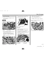
1. Measure the intake valve clearance by
inserting a feeler gauge (1) between the valve
lifters (2) and intake cam lobe (3).
2. Measure the exhaust valve clearance by
inserting a feeler gauge (1) between the
exhaust rocker arm (4) and shim (5).
(1) feeler gauge
(4) exhaust rocker arm
(5) exhaust vakve shim
Valve Clearances:
IN:
0.005 ± 0.001 in (0.12 ± 0.03 mm)
EX:
0.011 ± 0.001 in (0.28 ± 0.03 mm)
If intake valve clearance and exhaust valve
clearance need adjustment, see
Camshaft
Removal
(page 68) and select the correct shim for
each valve.
(6)
(1)
(3)
(2)
(5)
(1)
(4)
(1) feeler gauge
(2) valve lifters
(3) intake cam lobe
2. Rotate the crankshaft by turning the primary
drive gear lock bolt (3) clockwise until
aligning the “punch” mark (4) on the primary
drive gear with the index mark (5) on the right
crankcase cover. In this position, the piston may
either be on the compression or exhaust stroke.
If the crankshaft passed the “punch” mark,
rotate the primary drive gear lock bolt
clockwise again and align the “punch” mark
with the index mark.
The inspection must be made when the piston
is at the top of the compression stroke when
both the intake and exhaust valves are closed.
This condition can be determined by moving
the exhaust rocker arm (6). If it is free, it is an
indication that the valves are closed and that
the piston is on the compression stroke. If it is
tight and the valves are open, rotate the
primary drive gear lock bolt 360° and realign
the “punch” mark to the index mark.
(3)
(4)
(5)
(3) primary drive gear lock bolt
(5) index mark
(4) “punch” mark
(6) exhaust rocker arm
Servicing Your Honda
67
Summary of Contents for CRF250X
Page 1: ...HONDA CRF250X OWNER S MANUAL COMPETITION HANDBOOK ...
Page 3: ...2005 Honda CRF250X OWNER S MANUAL COMPETITION HANDBOOK ...
Page 12: ...6 Motorcycle Safety ...
Page 18: ...12 Before Riding ...
Page 28: ...22 Basic Operating Instructions ...
Page 152: ...146 Taking Care of Unexpected ...
Page 167: ...Technical Information 161 Wiring Diagram ...
Page 168: ...162 Technical Information ...
Page 179: ...Memo 173 ...


