Honda 2004 CRF450R Owner'S Manual Download Page 45

43

Piston Installation

Place clean shop towels in the crankcase to keep the
piston pin clips from falling into the crankcase.
Apply molybdenum disulfide oil (a mixture of 1/2 en-
gine oil and 1/2  molybdenum disulfide grease (con-
taining more than 3% molybdenum disulfide additive))
to the connecting rod small end.
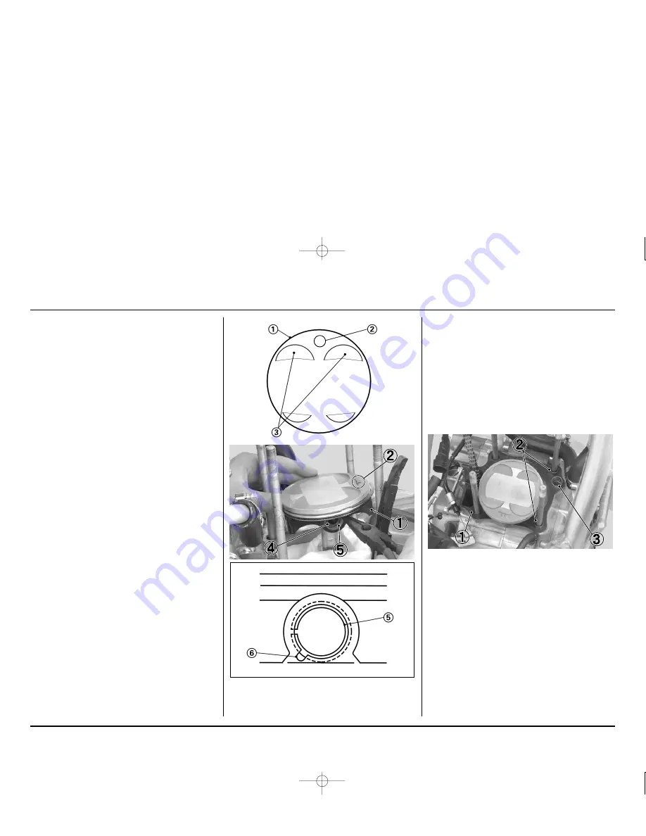
Install the piston with the “IN” mark and/or the large
valve recesses facing the intake side of the engine.
Apply flesh engine oil to the piston pin.
Install the piston pin and new piston pin clips.

CAUTION:

Use new pin clips. Never reuse old clips.

Do not let the clips fall into the crankcase.

Do not align the piston pin clip end gap with the
piston cut-out.

(1)  PISTON

(2)  “IN” MARK

(3)  LARGE VALVE RECESSES
(4)  PISTON PIN

(5)  PISTON PIN CLIP

(6)  CUT-OUT

Cylinder Installation

Clean off any gasket material from the gasket surface
of the crankcase, being careful not to let any material
fall into the crankcase.

NOTE:

Be careful not to remove any metal from the gasket
surface.

Remove the shop towel. Do not let any gasket debris
fall into the crankcase.
Install cylinder gasket, A dowel Pins and B dowel pin.

CAUTION:

Do not let the dowel pins fall into the crankcase.

(1)  CYLINDER GASKET
(2)  A DOWEL PINS
(3)  B DOWEL PIN

Clean the any gasket material off the cylinder.

IN

Summary of Contents for 2004 CRF450R

Page 1: ...atest product information available at the time of approval for printing Honda Motor Co Ltd reserves the right to make changes at any time without notice and without incurring any obligation No part o...

Page 2: ...nual for your CRF is available from your authorized Honda dealer It is the same manual your dealer uses If you plan to do any service on your CRF beyond the standard maintenance procedures included in...

Page 3: ...Idle Speed 26 CONTENTS Crankcase Breather 27 Air Cleaner 27 Clutch 28 Valve 30 Piston Piston Rings Piston Pin 39 Handlebar And Steering Head Bearings 47 Throttle Grip 47 Fuel Line 48 Front And Rear W...

Page 4: ...ng the engine page 21 23 24 Cold Engine Starting 1 Turn the fuel valve ON 2 Shift the transmission into neutral 3 If the temperature is 35 C 95 F or below pull the choke knob fully out 4 If the temper...

Page 5: ...tle 4 As soon as the engine starts release the hot start lever Stopping The Engine 1 Shift the transmission into neutral 2 Turn the fuel valve OFF 3 Lightly open the throttle 2 3 times and then close...

Page 6: ...4 1 OPERATING INSTRUCTIONS CONTROLS CLUTCH LEVER HOT START LEVER FRONT BRAKE LEVER ENGINE STOP BUTTON FUEL FILL CAP THROTTLE GRIP CHOKE KNOB FUEL VALVE SHIFT LEVER KICKSTARTER REAR BRAKE PEDAL...

Page 7: ...e clutch lever position adjustment or clutch cable disconnected 1 The clutch lever position can be adjusted by looseing the lock nut and turning the adjuster Turning the adjuster counterclockwise move...

Page 8: ...lever 1 HOT START LEVER 2 DUST COVER 2 Adjustments can be made with the cable end ad juster Loosen the lock nut and turn the adjuster Turning the adjuster in direction A will increase free play and tu...

Page 9: ...nterclockwise moves the brake lever closer to the grip Tighten the lock nut securely If the brake lever free play exceeds 0 8 in 20 mm there is probably air in the brake system and it must be bled Ref...

Page 10: ...courses there is a more durable steel driven sprocket with the standard number of teeth Like the optional springs these sprockets are listed in the optional parts section of this manual 1 CONTROL LEVE...

Page 11: ...oil filter change After disassembly After disassembly Transmission oil capacity After draining Type Identification number Main jet standard Jet needle standard Piston valve FCR00C 165 NCYR Needle cli...

Page 12: ...eedle NCYR 2 755 mm NCYS 2 765 mm NCYT 2 775 mm NCVT 2 775 mm CARBURETOR Remarks Main jet Standard 165 Slow jet Standard 42 155 175 in increments of 2 or 3 38 48 in increments of 2 or 3 Jet Needles St...

Page 13: ...TTLE OPERATION HOT START SYSTEM AIR FILTER CRANKCASE BREATHER SPARK PLUG RADIATOR COOLANT VALVE CLEARANCE DECOMPRESSOR SYSTEM ENGINE OIL ENGINE OIL FILTER ENGINE IDLE SPEED PISTON AND PISTON RINGS PIS...

Page 14: ...fications are listed on page 9 WARNING BETWEEN MOTO BETWEEN PRACTICE AND MOTO MAINTENANCE Dirt wear and weight Clean accumulated dirt from under fenders and off of wheels suspension grips controls and...

Page 15: ...s such as the brake and clutch lever pivot points and footpeg pivot pins WARNING Routine Cleaning If the machine is only slightly dirty it is best to clean it by hand with the aid of a stiff bristled...

Page 16: ...or an equivalent is handy for this because any dirt that penetrates this sealing area will show up clearly page 27 Use the Honda genuine air cleaner or an equivalent air cleaner specified for your mo...

Page 17: ...and the handlebar thoroughly and apply a light coating of silicone lubricant Inspect the cable carefully for kinks or other damage that may restrict throttle con trol in anyway Move the handlebar from...

Page 18: ...ary Look for cool ant or oil leakage Leaking coolant indicates a worn or damaged water seal Leaking oil indicates a bad transmission oil seal If replacement is necessary both seals should be replaced...

Page 19: ...ORQUE 20 lbf ft 26 N m 2 7 kgf m FUEL TANK Fuel Tank Removal 1 Turn the fuel valve OFF 2 Remove the seat this page 3 Remove the shroud A bolts and collars 4 Remove the shroud B bolts collars and shrou...

Page 20: ...is drained or stored and where the fuel tank is refueled Fuel Tank Installation 1 Install the fuel tank on the frame 2 Install the fuel valve and fuel valve bolt 3 Connect the fuel line 6 Put the brea...

Page 21: ...B bolt and subframe mount ing A bolts TORQUE B bolt 22 lbf ft 30 N m 3 1 kgf m A bolt 36 lbf ft 49 N m 5 0 kgf m 1 SEAT 2 SIDE COVER BOLTS COLLARS 3 SIDE COVER 3 Loosen the muffler clamp bolt 4 Remove...

Page 22: ...SCREW 2 AIR CLEANER CONNECTING TUBE CLAMP 3 CRANKCASE BREATHER TUBE 4 Remove the gasket 5 Install the muffler clamp and new gasket to exhaust pipe 1 MUFFLER 2 MUFFLER B BOLT 3 MUFFLER A BOLT 4 MUFFLE...

Page 23: ...oil filler cap from the left crank case cover 4 Place an oil drain pan under the engine to catch the oil Then remove the engine oil drain bolt and seal ing washer 5 With the engine stop button pushed...

Page 24: ...G 6 OIL FILTER COVER 7 OIL FILTER COVER BOLTS 15 Install the left engine guard and left engine guard bolt 4 SERVICE AND MAINTENANCE Other viscosities shown in the chart below may be used when the aver...

Page 25: ...the right crankcase cover A small amount of oil should flow out of the oil check bolt hole Al low any excess oil to flow out of the oil check bolt hole If no oil flows out of the oil check bolt hole...

Page 26: ...O T 903 standard is an index to choose engine oils for 4 stroke motorcycle engines There are two classes MA and MB Oil conforming to the standard has the following clas sification on the oil container...

Page 27: ...lean the spark plug If an electrode is con taminated with accumulated objects or dirt replace the spark plug with a new one Use only a wire type feeler gauge to check the spark plug if necessary To pr...

Page 28: ...a wrench until the sealing gasket is com pressed 1 2 turn to compress a new spark plug gas ket 1 8 1 4 turn to compress a spark plug with a used gasket 8 Connect the spark plug cap 9 Install the fuel...

Page 29: ...B 6 Wash the air cleaner in clean non flammable clean ing solvent Then wash in hot soapy water rinse well and allow to dry thoroughly 7 Clean the inside of the air cleaner housing WARNING Never use ga...

Page 30: ...ate Removal Drain the transmission oil page 23 Remove the rear brake pedal by removing its pivot bolt 1 REAR BRAKE PEDAL 2 PIVOT BOLT Remove the six clutch cover bolts and cover 1 CLUTCH COVER BOLTS 2...

Page 31: ...2 85 mm NOTE Replace the clutch discs and clutch plates as an as sembly 1 CLUTCH DISC Clutch Disc Plate Installation Coat the clutch plates with transmission oil Install the six clutch discs which ha...

Page 32: ...pivot bolt and tighten the pivot bolt TORQUE 20 lbf ft 26 N m 2 7 kgf m 1 BRAKE PEDAL 2 PIVOT BOLT 3 RETURN SPRING Add the transmission oil page 23 1 BREATHER TUBE 2 SPARK PLUG CAP Remove the cylinde...

Page 33: ...E GEAR LOCK BOLT 2 T MARK 3 INDEX MARK 4 EXHAUST ROCKER ARM 1 FEELER GAUGE 2 INTAKE VALVES VALVE LIFTERS 3 CAMSHAFT Measure the exhaust valve clearance by inserting a feeler gauge between the exhaust...

Page 34: ...tool until it stops in order to retract the tensioner fully Then insert the stopper tool fully to hold the stopper in the fully retracted position 4 SERVICE AND MAINTENANCE 1 STOPPER TOOL 12 0 mm Cam...

Page 35: ...emove the camshaft holder assembly the in take valve lifter and the intake valve shim may be stick ing in the camshaft holder assembly NOTE Loosen the camshaft holder assembly bolts in a criss cross p...

Page 36: ...shim with the micrometer Reface the intake valve seat if carbon deposits result in a calculated dimension of over 2 450 mm Reface the exhaust valve seat if carbon deposits result in a calculated dimen...

Page 37: ...t be inserted the shim is caught between the valve lifter and the valve retainer Remove the camshaft holder assembly place the shim correctly and reinstall the camshaft holder assembly Rotate the prim...

Page 38: ...e index mark Make sure that the timing marks on the sprocket align with the mark on the camshaft holder assembly If the timing mark doesn t align with the mark re move the cam sprocket Then realign th...

Page 39: ...nstall the new sealing washer and cam chain tensioner lifter cover bolt 1 SEALING WASHER 2 CAM CHAIN TENSIONER LIFTER COVER BOLT Decompressor Arm Clearance Adjustment Make sure that the piston is at t...

Page 40: ...g hole 1 SPARK PLUG HOLE PACKING 2 SPARK PLUG HOLE Install the cylinder head packing into the groove of the cylinder head cover Loosen the lock nut and adjusting screw Insert the feeler gauge right ex...

Page 41: ...17 Remove the fuel tank pate 17 Remove the muffler and subframe page 19 Remove the carburetor page 62 Remove the exhaust pipe joint nuts exhaust pipe and exhaust pipe gasket 1 EXHAUST PIPE JOINT NUTS...

Page 42: ...guide Remove the engine hanger B bolts left engine hanger plate and right engine hanger plate 1 ENGINE HANGER NUT 2 ENGINE HANGER A BOLT 3 RIGHT COLLAR 4 LEFT COLLAR 5 FUEL HOSE GUIDE 6 ENGINE HANGER...

Page 43: ...g Spread each piston ring and remove by lifting it up at a point just opposite the gap CAUTION Do not damage the piston ring by spreading the ends too far Remove the dowel pins cylinder head gasket an...

Page 44: ...N Do not damage the piston ring by spreading the ends too far Do not damage the piston during piston ring instal lation NOTE To install the oil ring install the spacer first then install the side rail...

Page 45: ...lips Never reuse old clips Do not let the clips fall into the crankcase Do not align the piston pin clip end gap with the piston cut out 1 PISTON 2 IN MARK 3 LARGE VALVE RECESSES 4 PISTON PIN 5 PISTON...

Page 46: ...ylinder walls Install the cam chain guide and fit the cam chain guide tabs in the cylinder cut outs Push the guide until bottoms in the crankcase guide hole Cylinder Head Installation Install the dowe...

Page 47: ...10 N m 1 0 kgf m 1 LEFT ENGINE HANGER PLATE 2 RIGHT ENGINE HANGER PLATE 3 ENGINE HANGER B BOLTS 4 ENGINE HANGER A BOLT 5 FUEL HOSE GUIDE 6 LEFT COLLAR 7 RIGHT COLLAR 8 ENGINE HANGER NUT 1 CYLINDER HE...

Page 48: ...E 2 RADIATOR HOSE CLAMP Install the shims and cam shaft holder assembly page 34 Install the spark plug with a spark plug wrench until finger tight then tighten with a spark plug wrench until the seali...

Page 49: ...eering head bearings Now stand in front of your CRF and grab the fork at the axle then push the fork in and out toward the engine to check for play in the steering head bearings If any roughness or pl...

Page 50: ...17 3 Disconnect the fuel line 4 Remove the fuel filter by removing the bolts Wash the fuel filter in high flash point cleaning solvent 5 Reassemble the fuel filter in the reverse order of re moval Mak...

Page 51: ...1 Make sure that the fork protectors and dust seals are clean and not packed with mud and dirt 2 Check for signs of oil leakage Damaged or leaking fork seals should be replaced before your CRF is rid...

Page 52: ...pring preload and damping ad justments compression and rebound should be ad justed for the rider s weight and track conditions See Section 6 The rear shock absorber assembly includes a damper unit tha...

Page 53: ...d Whenever the fluid level is near the lower mark on the reservoir fill it with DOT 4 BRAKE FLUID from a sealed container Remove the bolts reservoir cap and dia phragm Add the brake fluid to the upper...

Page 54: ...under the engine and shift the trans mission into neutral 2 Check slack in the drive chain midway between the sprockets above the swingarm Drive chain slack should allow 1 1 3 8 in 25 35 mm of vertic...

Page 55: ...the distance between a span of 17 pins from pin center to pin center If the measurement exceeds the service limit replace the chain After the chain is measured shift the trans mission into neutral ag...

Page 56: ...ay be purchased at most motorcycle shops and should be used in preference to motor oil Pro Honda Chain Lube or an equivalent or SAE 80 or 90 gear oil is recommended Saturate each chain joint so that t...

Page 57: ...er for cracks or deformation A damaged exhaust pipe and muffler may reduce engine performance Muffler Removal 1 Remove the seat bolt collar side cover bolt collar and right side cover 2 Loosen the muf...

Page 58: ...l the muffler 4 Install the muffler clamp by aligning the tab of the muffler clamp with the cut out of the muffler 1 RIGHT SIDE COVER 2 SIDE COVER BOLT 3 SEAT BOLT 4 COLLARS 1 MUFFLER 2 MUFFLER B BOLT...

Page 59: ...ally disconnect the throttle clutch and hot start cables at their upper ends Thoroughly lubricate the cable pivot points and the inside of clutch cable end adjuster with a commercially available cable...

Page 60: ...ap Oil filter cover Cylinder bolt Cylinder head bolt Exhaust pipe joint nut Torque Remarks lbf ft N m kgf m 7 7 7 7 11 9 7 7 15 10 10 10 10 15 12 10 10 21 1 0 1 0 1 0 1 0 1 5 1 2 1 0 1 0 2 1 NUTS BOLT...

Page 61: ...ar shock arm nuts swingarm side shock link side Rear shock link nuts Frame side Shock spring lock nut Kickstarter arm bolt Torque Remarks lbf ft N m kgf m 80 17 15 16 33 65 14 94 20 40 40 20 40 20 33...

Page 62: ...eat mounting bolts Front brake resevroir cap screws Rear brake reservoir cap bolts Fork air plugs Torque Remarks lbf ft N m kgf m 7 25 22 12 12 20 2 7 9 4 22 36 51 16 9 5 1 16 16 15 24 20 1 1 1 1 0 9...

Page 63: ...it A lean mixture must be delivered to the cylinder when hot engine is being started When the hot start lever is pulled back the hot start valve opens allowing air is supplied to the main bore through...

Page 64: ...wl Disassembly Assembly 1 Turn the fuel valve OFF 2 Drain the remaining fuel in the float bowl by remov ing the float bowl plug Removing the float bowl plug will allow the fuel in the float bowl to dr...

Page 65: ...E BAND SCREW 8 Disconnect the throttle sensor connector 9 Remove the carburetor 1 THROTTLE SENSOR CONNECTOR 1 HOT START CABLE HOLDER 11 Remove the hot start valve spring and hot start cable holder fro...

Page 66: ...t needle holder and jet needle from the throttle valve 1 JET NEEDLE HOLDER 2 JET NEEDLE 3 THROTTLE VALVE 1 FLOATING VALVE 2 THROTTLE VALVE 3 HOLE 16 Remove the link arm set screw When installing the l...

Page 67: ...Measure the float level with the float tab just con tacting the float valve and the carburetor intake fac ing up The float level should be 0 31 in 8 0 mm Adjust the float level by bending the float t...

Page 68: ...HROTTLE CABLES 2 HOT START CABLE 3 THROTTLE SENSOR CONNECTOR 5 CARBURETOR ADJUSTMENT Pre adjustment Checks Before adjusting carburetor settings check the follow ing 1 air cleaner condition page 27 2 a...

Page 69: ...and slow jet as required 1 MAIN JET 2 SLOW JET 12 Reinstall the float bowl plug Adjustment Procedure 1 Turn the pilot screw in until it is lightly seated and record the number of turns Turn the pilot...

Page 70: ...d ing It is always better to jet a little rich than a little lean It is advisable to record the settings course conditions lap times and climatic and barometric conditions for future reference 1 SLOT...

Page 71: ...00C Main Jet The main jet affects fuel air ratio from half to full throttle 4 4 The size should be reduced at higher altitudes NOTE Honda carburetor jet sizes are numbered in incre ments of 2 or 3 Whe...

Page 72: ...9 60 59 80 79 100 99 120 STANDARD JETTING 5 CARBURETOR ADJUSTMENT TUNING FOR SPECIAL CONDITIONS Once you ve adjusted the carburetor for temperature and altitude it shouldn t need major readjustment un...

Page 73: ...the Unloaded dimension when your CRF s is supported by a workstand without the left side cover and the rear wheel is off the ground Measure the dis tance from the center of the rear fender mounting bo...

Page 74: ...llation of optional rate fork springs as well in order to maintain proper front rear suspension balance These and other com ponents are listed in the Optional Parts section of this manual Keep in mind...

Page 75: ...compression adjuster To adjust the high speed compression damping to the standard proceed as follows Turn the adjuster clockwise until it will no longer turn Iightly seats This is the full hard positi...

Page 76: ...lso isolates the oil in each fork tube slider which may contain air bubbles and or metal particles from the sealed cartridge to provide more consistent damping Fork Springs The fork springs in CRF s a...

Page 77: ...ster is set in the standard position when the adjuster is turned counterclockwise 11 clicks Make sure that both fork legs are adjusted to the same position NOTE Both compression and rebound damping ca...

Page 78: ...TS 2 FORK DAMPER Loosen the upper pinch bolts Loosen the fork dampers but do not remove them yet CAUTION Do not use an adjustable wrench to loosen the fork damper it may damage them Loosen the upper p...

Page 79: ...ork protector and brake caliper CAUTION Do not support the brake caliper by the brake hose Do not operate the brake lever after the front wheel is removed To do so will cause difficulty in fitting the...

Page 80: ...5 55 8 3 9 4 12 9 16 5 85 7 9 8 2 11 8 15 3 145 7 9 8 2 11 8 14 1 Pour the fork oil from the outer tube Pour the fork oil from the oil hole of the fork damper 1 OUTER TUBE 2 OIL HOLE Drain the fork o...

Page 81: ...nears full compression Minimum oil capacity 10 9 US oz 322 cm3 Optional Softer 0 45 kgf mm Fork Spring Standard oil capacity 14 0 US oz 413 cm3 Maximum oil capacity 14 1 US oz 417 cm3 Slightly stiffe...

Page 82: ...lts and then tighten the fork damper to the specified torque using a special tool TORQUE 25 Ibf ft 34 N m 3 5 kgf m For ease of releasing air pressure after the forks are installed Ioosen the lower pi...

Page 83: ...urface Tighten the axle nut TORQUE 65 Ibf ft 88 N m 9 0 kgf m Align the brake caliper and hose with the left fork leg making sure that the brake hose is not twisted Clean the threads of the caliper mo...

Page 84: ...E 9 Ibf ft 13 N m 1 3 kgf m 1 BOLTS 2 DISC COVER Turn the rebound damping adjusters back to their origi nal settings 6 SUSPENSION ADJUSTMENT Install the handlebar mounting rubbers washers and handleba...

Page 85: ...ock nut Hold the lock nut and remove the fork center bolt from the fork damper CAUTION Do not remove the lock nut from the fork damper piston rod If the lock nut is removed the piston rod will fall in...

Page 86: ...E Be careful not to damage the fork cap bushing Do not disassemble the fork cap assembly Replace the fork cap as an assembly if it is dam aged 1 PUSH ROD 3 TOOL 2 LOCK NUT 4 AXLE HOLDER Remove the for...

Page 87: ...er piston rod slowly several times to bleed the air from the fork damper 1 FORK DAMPER 2 PISTON ROD 1 FORK DAMPER Apply fork oil to the bushing and new O ring on the fork cap assembly Extend the fork...

Page 88: ...d adjuster and compression adjuster counterclockwise to the softest position Check the fork damper piston rod sliding surface for damage Apply fork oil to the fork damper piston rod sliding surface Co...

Page 89: ...minute C F 30 86 20 68 10 50 0 32 5 7 1 10 6 11 8 12 9 10 5 9 8 2 8 3 10 6 20 4 7 7 1 7 2 9 4 35 4 2 5 9 6 2 8 2 55 3 5 5 6 5 8 7 9 85 3 5 4 7 4 9 7 1 145 3 5 4 7 4 8 5 9 Tighten the lock nut fully a...

Page 90: ...Measure the length of the lock nut and center bolt clear ance STANDARD 0 06 0 08 in 1 5 2 0 mm If the clearance is out of specification check the lock nut and center bolt installation Apply fork oil t...

Page 91: ...tandard oil capacity 13 8 US oz 409 cm3 Maximum oil capacity 14 1 US oz 416 cm3 Slightly stiffer as it nears full compression Slightly softer as it nears full compression Minimum oil capacity 10 8 US...

Page 92: ...ts probably won t change much between a hard track and a sand track You may want a little bit stiffer front suspension for sand tracks to help keep the front end up and improve straight line stability...

Page 93: ...Test stiffer compression damping adjustments in one click increments If initial travel becomes stiff because of the above adjustment Reduse the rebound damping in one click increments Test softer comp...

Page 94: ...crements Reduce the rebound damping in one click increments If initial and middle travel aren t stiff Test stiffer compression damping adjustments in one click increments This should produce smooth fo...

Page 95: ...til the correct settings are obtained as described Suspension feels stiff on small bumps 1 Test softer high speed compression adjustment 2 If it still feels stiff further test softer low and high spee...

Page 96: ...djustments for more or less trail as mentioned eariler You must realize that these chassis adjustments offer subtle changes in over all handling yet a noticeable improvement will be real ized in the a...

Page 97: ...e pants feelings can t be trusted since elimi nating wheelspin can make you feel like you re going slower but in reality you ve decreased your lap time by increasing your speed a little bit in each se...

Page 98: ...nges Chain Sprocket Chain Guide and Slider Replace ments Coolant Changes and Related Component Replace ments Spark Plug Brake Pad and Control Cable Replace ments In addition you should record any irre...

Page 99: ...ANCE TUNING RACING LOGBOOK 20 CRF Make several photocopies of this page for future use Date Comments Jetting Suspension Settings Gearing Chassis Adjustments Maintenance Performed etc Running Time Loca...

Page 100: ...c scale click stop style Pliers Standard Needle Nose Channel Lock Type Hammer Plastic Head Syringe With Adjustable Stop Tire Pressure Gauge Tire Irons Tire Pump or Air Tank BASIC TOOLS Drop Light Feel...

Page 101: ...oken or shorted spark plug wire 6 Faulty ignition pulse generator 1 Ring worn 2 Cylinder worn or damaged 3 Piston worn or damaged 4 Head gasket not sealing POOR PERFORMANCE AT HIGH SPEED CHECK POSSIBL...

Page 102: ...Several ap plications may be necessary to restore normal brak ing performance Braking performance may be impaired immediately after washing your CRF Aluminum Frame Maintenance Aluminum corrodes when i...

Page 103: ...adiator cap Install the right engine guard and bolt REMOVAL FROM STORAGE 1 Uncover and clean your CRF Change the engine oil and transmission oil if more than 4 months have passed since the start of st...

Page 104: ...102 15 WIRING DIAGRAM...

Page 105: ...service information 12 Handlebar and steering head bearings 47 Handlebar position width shape 8 Hot start 6 Ignition 26 Maintenance preparations 17 Maintenance procedures 21 Maintenance schedule 11 Ma...

Page 106: ...104 MEMO...

Page 107: ...ject to change without notice and without incurring obligation Orders are mailed within 10 days Please allow adequate time for delivery Sub Total Grand Total Mich Purchases Add 6 Sales Tax Handling Ch...

Page 108: ...106 MEMO...

Reviews: