background image

15

HOMEDEPOT.COM/HUBSPACE

Please contact 1-877-592-5233 for further assistance.

Operating Your Fan and Remote Control

POWER ON/OFF

Press and release the power button to turn the fan and light on or off.

LIGHT ON/OFF/DIMMING

Press and release the button to turn the light on or off.

Press and hold the button to activate the dimmer function.

CORRELATED COLOR TEMPERATURE (CCT) CHANGING

Push and release the button to cycle through the six color temperature 
options.

Option 1: 2700K (Warm White).

Option 2: 3000K (Soft White).

Option 3: 3500K (Neutral White).  

Option 4: 4000/4100K (Cool White).   

Option 5: 5000K (Daylight).

Option 6: 6500K (Cool Daylight).

NOTE:

 The default temperature of the ceiling fan light is 3000k 

(Soft White).

Power
(fan and light on/off)

Light on/off/dimming

Fan speed

CCT changing

Fan reverse

FAN SPEED

LEDs on the fan speed button will illuminate to the corresponding speed.

Press and release 1 time: turns the fan speed to 5.

Press and release 2 times: turns the fan speed to 4.

Press and release 3 times: turns the fan speed to 3.

Press and release 4 times:  turns the fan speed to 2.

Press and release 5 times:  turns the fan speed to 1.

Press and release 6 times: turns the fan off.

NOTE:

 The remote receiver includes a memory function that will 

return the fan to its last setting when turned on via the power 
button.

FAN REVERSE

Press and release the fan reverse button to reverse the rotation of your 
ceiling fan.

A. Warm weather (Forward) - A downward airflow creates a cooling 
effect. This allows you to set your air conditioner on a higher setting 
without affecting your comfort.

B. Cool weather (Reverse) - An upward airflow moves warm air off of the 
ceiling. This allows you to set your heating unit on a lower setting without 
affecting your comfort.

NOTE:

 Do not wait for the fan to stop before pressing the reverse 

button. The fan will not reverse direction if the fan is not moving.

A. Warm weather

B. Cool weather

NOTE:

 On start up your ceiling fan will oscillate back and forth. 

This is NORMAL OPERATION for DC ceiling fans as it goes 
through its calibration cycle. The fan is NOT DEFECTIVE.

Summary of Contents for 56052

Page 1: ... UL Model 60 SNYD USE AND CARE GUIDE DRISKOL 60 INCH CEILING FAN To view an instructional video on how to install this product 1 Go to www homedepot com and enter either the Item or Model number found in the top right corner of the cover of this instruction manual in the search field 2 Click on your product from the list of search results and click on the video link in the Product Overview section ...

Page 2: ...uctor on one side of the outlet box 8 All set screws must be checked and retightened where necessary before installation WARNING To reduce the risk of personal injury do not bend the blade brackets also referred to as flanges during assembly or after installation Do not insert objects in the path of the blades WARNING Electrical diagrams are for reference only If you are using a light kit refer to...

Page 3: ...removing and reinstalling the product are your responsibility Damage to any part such as by accident misuse improper installation or by affixing any accessories is not covered by this warranty Because of varying climatic conditions this warranty does not cover any changes in brass finish including rusting pitting corroding tarnishing or peeling Brass finishes of this type give their longest useful...

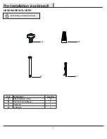
Page 4: ...scription Quantity AA Blade attachment screws 16 BB Plastic wire connecting nut 3 CC Hanger pin 1 DD Locking pin 1 Pre Installation continued HARDWARE INCLUDED NOTE Hardware not shown to actual size BB CC DD AA ...

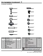
Page 5: ...t fitter assembly 1 Part Description Quantity I Shatter resistant shade 1 J Receiver 1 K Remote control 1 L 3 pin extension wire 66 in 1 M 2 pin extension wire 66 in 1 N Battery 2 O Shorter 3 pin extension wire 12 in 1 P Shorter 2 pin extension wire 12 in 1 IMPORTANT This product and or components are governed by one or more of the following U S Patents 5 947 436 5 988 580 6 010 110 6 046 416 6 21...

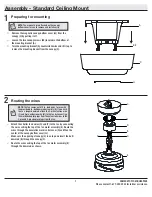
Page 6: ...et box and support structure must be securely mounted and capable of reliably supporting a minimum of 35 lbs 15 9 kg Use only UL listed outlet boxes marked Acceptable for fan support of 35 lbs 15 9 kg or less Do not use a plastic outlet box The illustrations below show three different ways to mount the outlet box If the canopy touches the downrod then remove the decorative canopy bottom cover and ...

Page 7: ... Route the wires through the decorative motor collar cover D and then the center of the canopy bottom cover JJ Make sure the opening of canopy C is on top and insert the ball downrod B through the canopy C Route the wires exiting the top of the fan motor assembly E through the downrod as shown 2 1 NOTE The fan comes with 12 in lead wires for use with the provided 6 in ball downrod assembly B If yo...

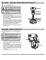
Page 8: ...ly Standard Ceiling Mount continued Assembling the fan Loosen but do not remove the setscrew KK on the collar PP on top of the fan motor assembly E Install the downrod B by inserting it into the motor collar PP and turning it clockwise until the holes at the bottom of the ball downrod assembly B align with the holes in the collar on top of the fan motor assembly E Carefully insert the hanger pin C...

Page 9: ... kit will flash and the blades will begin to spin Replace the battery cover on the remote control 1 to 3 mode To use more than one remote control for your fan press the Learn button for 10 seconds and release Once pairing is successful the fan s light kit will flash and the blades will begin to spin Repeat the above process for the remote controls you want to work with this fan The fan can be only...

Page 10: ...u do not have enough electrical wiring knowledge or experience contact a licensed electrician WARNING Each wire nut supplied with this fan is designed to accept up to one 12 gauge house wire and two wires from the fan If you have larger than 12 gauge house wiring or more than one house wire to connect to the fan wiring consult an electrician for the proper size wire nuts to use IMPORTANT Use the w...

Page 11: ...unting the tab in the ring at the bottom of the mounting bracket must rest in the groove of the hanger ball Failure to properly seat the tab in the groove could cause damage to the wiring NOTE The magnet is pre attached on the canopy bottom cover for you to remove and install easily Align the locking slots of the canopy C with the two screws EE and alignment post QQ in the mounting bracket A Push ...

Page 12: ...the screw FF that was removed in the first step Make sure all the screws are firmly tightened Assembly Attaching the Fan Blades Attaching the fan blades 1 Attach a blade F to the fan motor assembly E by inserting the blade F into slots in the side of the fan motor assembly E and aligning the three screws holes in the blade with the holes in the center flywheel and secure with screws AA Make sure a...

Page 13: ...up to the light kit pan G so that the two loosened screw heads fit into the keyhole slots Turn the light kit fitter assembly H clockwise to secure Re install the screw that was removed in the first step Make sure all the screws are firmly tightened Installing the shatter resistant shade 3 Place the shatter resistant shade I into the light kit pan G aligning the three flat areas on the top of the f...

Page 14: ...attach it to the wall using the included wall cradle screws Slide the screw cover plate back onto the wall cradle to conceal the screws Screw cover plate NOTE Screw wall anchors are included for extra support The included screws are designed to screw easily into the wall If you would like a more permanent or secure hold install the wall anchors prior to attaching the wall cradle to the wall ...

Page 15: ...ase 2 times turns the fan speed to 4 Press and release 3 times turns the fan speed to 3 Press and release 4 times turns the fan speed to 2 Press and release 5 times turns the fan speed to 1 Press and release 6 times turns the fan off NOTE The remote receiver includes a memory function that will return the fan to its last setting when turned on via the power button FAN REVERSE Press and release the...

Page 16: ...outer settings Verify your network 2 In the Hubspace app tap the plus sign in the upper right corner Scan your product s QR code You can find the QR code on the remote receiver inside the battery compartment cover of the remote and on the Quick Start Guide paper included with the fan Add a device 3 If you are unable to access the QR code for your light you can put it into discovery mode with the f...

Page 17: ...e Turn on Comfort Breeze on device name Alexa When you want to Ask Google to Turn on the fan only turn on device name fan power Turn off the fan only turn off device name fan power Turn on the light only turn on device name light power Turn off the light only turn off device name light power Change the brightness Set device name brightness to 75 Set device name light to 25 Brighten device name Dim...

Page 18: ...ecure and rubber isolator pads were used between the mounting plate and outlet box The fan wobbles Check that all blade and blade arm screws are secure Most fan wobble problems are caused when blade levels are unequal Check this level by selecting a point on the ceiling above the tip of one of the blades Measure from a point on the center of each blade to the point on the ceiling Rotate the fan un...

Page 19: ...easures Reorient or relocate the receiving antenna Increase the separation between the equipment and receiver Connect the equipment into an outlet on a circuit different from that to which the receiver is connected Consult the dealer or an experienced radio TV technician for help CAUTION Any changes or modifications not expressly approved by the grantee of this device could void the user s authori...

Reviews: