32 | EngliSH
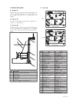
3.3.5. Propeller
A self cleaning propeller from stainless steel is used.
3.3.2. Motor
The three-phase asynchronous motor is made from sheet
metal with a double-varnished winding wire as well as the
motor shaft with rotor package. The power supply cable is
designed for the maximum mechanical load and is sealed
against water pressure from the pumped liquid. The mo-
tor cable lead connections are sealed from the pumped
liquid as well. The bearings used are permanently lubricat-
ed maintenance-free antifriction bearings.
All models are available with explosion proof motors.
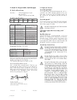
General motor data
Operating mode
S1
Insulation class
F (155°C)
Degree of protection
IP68
Cable length
10 m
Shaft sealing HRS
NBR
Bearing
one grooved ball bearing (suspension side)
one double-row type angular ball bearing
(propeller side)
3.3.3. Control devices
The pump is equipped with various safety and control de-
vices:
Temperature Sensors
The mixers have a set of temperature sensors built in the
stator windings.
Standard models have the sensors connected to the mo-
tor power supply cable, the wire ends marked T1 and T3.
They must be connected to the safety circuit of the con-
trol box in order to provide an automatic re-start of the mo-
tor, when the motor cools. Explosion proof models with
motors up to 15 kW have a set of temperature sensors
built-in, with a higher switch-off temperature, connected
to the motor cable, the wire ends marked T1 and T2. They
must be connected to a special relay in the starter box in
order to provide manual pump re-start. All explosion proof
models have both sets of sensors built-in, as described
above, with wire ends marked T1, T2, T3. They have to be
connected accordingly as described above. The tempera-
ture sensor set must be connected to the switchgear unit
so that it switches off if it overheats.
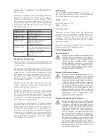
Check of Direction of Rotation
After the electrical connection has been made, check that
the agitator propeller is rotating in the correct direction.
As seen from the motor, the propeller must rotate clock-
wise. If you ordered a special version with left-hand drive,
the propeller must turn counter-clockwise. If the direction
of rotation of the agitator propeller is incorrect, transpose
two of the three conductor phases (L1, L2, L3) coming
directly from the mains.
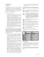
Beware of rotating propeller!
The moving propeller can crush and sever limbs.
Switch off the machine and let the moving parts
come to a rest before maintenance or repair work!
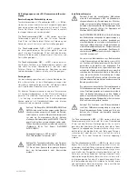
Seal condition sensors oil chamber
Agitator motors in the HRS…/C and CHRS…/C series are
fitted as standard with monitoring of the sealing of the oil
barrier chamber. Two sensors monitor the conductibility
of the oil filling. The sensors are to be connected via the
connecting cables with the cable-end designations S1 and
S2 in the switchgear to an evaluation instrument with a
galvanically isolated sensor circuit (electrode relay). If the
shaft seal leaks, water enters the oil chamber and chang-
es the resistance of the oil. Response sensitivity should
be adjustable from 0-100 kÙ. The standard setting is 50
kÙ. If this is an antiexplosion design, select electrode re-
lays with intrinsically safe circuits for sensors.
Motor cooling
They are cooled by the surrounding liquid.
Summary of Contents for CHRS.../4 series
Page 25: ...DEUTSCH 25 Notizen Notes ...
Page 71: ...Nedlerlands 71 Notizen Notes ...
Page 75: ...75 ...

