background image

8

SAA Series | Version 1.06

Intended use

3

 Intended use

The Chip Extraction Unit serves for the extraction of 
chips and dust which are produced when wood or wood-
like materials are processed. The Extraction Unit is con

-

structed for the application in not explosion-threatened 
surroundings and may be installed and operated in dry 
rooms only. The observance of all information in these 
instructions also belongs to the designated use. Every 
different use except of the designated use is considered 
as a false use. 

The exhaust system has not been designed for commer

-

cial, craft or industrial use. We do not assume any war

-

ranty if the machine is used in commercial, handicraft or 
industrial drives as well as in similar activities. 

Claims of any kind for damages caused by improper use 
are null and void. 

4

Technical Data

4.1 Table 

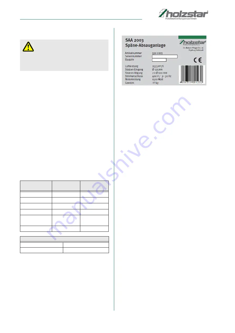
4.2 Type plate

Fig. 2: Type plate SAA 2003

5

Transport, packaging, storage

5.1 Delivery and transport

Check the Chip Extraction Unit for visible transport da

-

mage upon delivery. In case of visible damage to the 
Chip Extraction Unit, immediately notify the carrier or 
your retailer.

5.2 Packaging

All of the Chip Extraction Unit‘s packaging materials and 
packing aids are suitable for recycling and must always 
be disposed of using material-based recycling systems.

Packaging materials made of cardboard must be shred

-

ded and recycled as waste paper.

The foils are made of polyethylene (PE), padding is 
made of polystyrene (PS). Dispose of these substances 
at a recycling centre or hand them over to a qualified wa

-

ste disposal company.

5.3 Storage 

Always store the Chip Extraction Unit in a clean condition 
and a dry, clean and frost-free environment. It must not 
be stored in the same room as chemicals.

Cover the machine with a protective tarpaulin.

WARNING!

On not designated use of the aspiration system there 
will be generated dangers for the staff, the aspiration 
system and other objects of the operator, furthermore 
the function of the machine can be affected.

Model

SAA 2001/ 
SAA 2003

SAA 3001 / 
SAA 3003

Air flow rate

2.553 m

³

/h

3.910 m

³

/h

Duct input

Ø 

125 mm

Ø 

150 mm

Duct output

2 x 

Ø

100 mm

3 x 

Ø

100 mm

Motor output

1,5 kW

2,2 kW

Dimensions        
[L x W x H]

1.000 x 750 x 
2.000 mm

1.450 x 800 x 
2.000 mm

Weight

37 kg

48kg

Electrical connection:

SAA 2001/ SAA 3001 

230 V/50 Hz

SAA 2003 / SAA 3003

400 V/50 Hz

Summary of Contents for 5922201

Page 1: ...SAA 2001 Operating Instructions SAA S ERIES Chip Extraction Unit SAA 2001 SAA 2003 SAA 3001 SAA 3003 SAA 3001 ...

Page 2: ... equipment 5 2 5 Safety labels on the Chip Extraction Unit 5 2 6 General safety aspects 6 2 7 Safety aspects in dealing with electricity 6 2 8 Safety aspects in dealing with application of tools 7 2 9 Safety to operation 7 2 10 Safety aspects on servicing and maintenance 7 2 11 Security check 7 3 Intended use 8 4 Technical Data 8 4 1 Table 8 4 2 Type plate 8 5 Transport packaging storage 8 5 1 Del...

Page 3: ...e submit any information and experiences you make during application of the machine as these may be valuable for product improvements 1 3 Disclaimer All data in this operation manual has been compiled on the basis of the state of the art valid standards and gui delines as well as our many years of expertise and expe rience The manufacturer shall not be liable for damage in the following cases Fail...

Page 4: ...ipment shall be mandatory Operators shall also be responsible for maintaining the machine in a technically perfect condition For this rea son the following shall apply Operators shall make sure that the maintenance in tervals described in these operating instructions are complied with Operators shall regularly check that the safety equipment is fully functional and complete 2 3 Operating staff qua...

Page 5: ...t is described in the following section 2 5 Safety labels on the Chip Extraction Unit The following safety labels and instructions are attached to the Chip Extraction Unit s Fig 1 and must be observed Fig 1 Safety labels 1 Warning of dangerous electrical voltage 2 Safety instructions If safety labels on the machine are damaged or missing this can cause errors personal injury and material da mage T...

Page 6: ...t use the Extraction Unit if you are not concentrated 13 The operation or servicing of the Chip Extraction Unit is forbidden for people who are less than 18 years or are under influence of alcohol or drugs 14 Check the material to be worked on before starting the Extraction Unit and check about a possible health danger by released dust Take suitable precautions if necessary 15 While working with t...

Page 7: ...8 Never touch the machine during operation 9 Provide for good illumination 10 To avoid contact with the blower wheel unused exhaust connections must always be covered 11 While working outside good footwear is recommen ded 12 Keep the working area free of rubbish 13 All protective devices must be mounted immediately after servicing 2 10 Safety aspects on servicing and main tenance 1 After servicing...

Page 8: ...mediately notify the carrier or your retailer 5 2 Packaging All of the Chip Extraction Unit s packaging materials and packing aids are suitable for recycling and must always be disposed of using material based recycling systems Packaging materials made of cardboard must be shred ded and recycled as waste paper The foils are made of polyethylene PE padding is made of polystyrene PS Dispose of these...

Page 9: ...perator for ma terial transport and for adjustment and main tenance work The Chip Extraction Unit must be well grounded Mains voltage and frequency correspond to the values of the engine of the machine The installation location must have good illumina tion Pos Description Pos Description A Connector H Bag B Fan Motor assembly I Packing C Casing J Four casters D Base Plate K Nuts screws washers spr...

Page 10: ...od fixed 7 4 Electrical connection In the follow Steps the Chip Extraction Unit can con nected to the electricity network Step 1 The Chip Extraction Unit must be off Step 2 The Chip Extraction Unit SAA 2003 und SAA 3003 Model connect on the 400 V 3 phase connection Step 3 Check whether all protective devices are mounted Step 4 Switch on the Chip Extraction Unit Step 5 Check whether the direction o...

Page 11: ...ep 2 Install the packing and square connecting tube connector to the collector body assembly using screw and washers provided Fig 6 Fig 7 Fig 7 Installation of the fan motor assembly 3 Step 3 Install the two collectors and two packing to the outlet Fig 8 Fig 8 Installation of the fan motor assembly 4 Installation of the support rods Fig 9 Installation of the support rods 1 Step 1 Install the two c...

Page 12: ...perating To guarantee a long life the servicing aspects are to be carried out regularly ATTENTION Danger to life due to electrical shock Danger of live through electric shock by contact with live power components The Chip Extraction Unit may connected only from Qualified electrician Repairs on the electrical system must execute only from Qualified electrician Switch off the machine and pull the pl...

Page 13: ...for the lubricants used If necessary request productspeci fic data sheets IMPORTANT If one of the following malfunctions occurs immedi ately stop working with the machine Before you start troubleshooting turn off the machine and unplug the power plug Failure to do so can lead to serious injury All repairs or replacement work may be perfor med by qualified and trained expert staff only Malfunc tion...

Page 14: ...Always quote the following key data with your spare parts orders Device type Serial number Quantity Designation Desired shipping type post freight sea air ex press Shipping address Spare parts orders without the aforementioned data can not be taken into account The supplier shall determine the shipping type if no relevant data was provided Example You must order the fan base for the Chip Extractio...

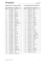
Page 15: ...rawings The following drawings are intended to help identify the necessary spare parts To order please send a copy of the part drawing with the marked components to your dealer Spare parts drawing SAA 2001 SAA 2003 Fig 11 Spare parts drawing SAA 2001 SAA 2003 ...

Page 16: ...16 SAA Series Version 1 06 Spare parts Spare parts drawing SAA 3001 SAA 3003 Fig 12 Spare parts drawing SAA 3001 SAA 3003 ...

Page 17: ...xx 34 Hose Clamp 35 0 xxxxxxx 35 Filter Bag 36 0 xxxxxxx 36 Collector Bag 37 0 xxxxxxx 37 Collector Support 38 0 xxxxxxx 38 Screw 39 0 xxxxxxx 39 Nut 40 0 xxxxxxx 40 Support Block Part No Article number Description 1 0 xxxxxxx 01 Caster 2 0 xxxxxxx 02 Screw 3 0 xxxxxxx 03 Screw 4 0 xxxxxxx 04 Base Plate 5 0 xxxxxxx 05 Screw 6 0 xxxxxxx 06 Inlet 7 0 xxxxxxx 07 Screw 8 0 xxxxxxx 08 Screw Hex 9 0 xxx...

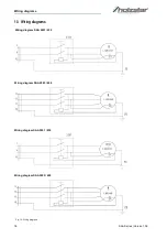
Page 18: ...18 SAA Series Version 1 06 Wiring diagrams 13 Wiring diagrams Fig 13 Wiring diagrams Wiring diagram SAA 2001 230 Wiring diagram SAA 2003 400 Wiring diagram SAA 3001 230 Wiring diagram SAA 3003 400 ...

Page 19: ...orresponds on the basis of its design and construction as well as the version that we have put into circulation with the relevant fundamental health and safety requirements of subsequent EU Directives Relevant EU Directives 2014 30 EU EMC Directive The following harmonized standards have been applied DIN EN ISO 12100 2010 Safety of machinery General principles for design Risk assessment and risk r...

Page 20: ...www holzstar de ...

Reviews: