


Rev. 1.50
90
����st ��� �01�
Rev. 1.50
91
����st ��� �01�
HT66F0175/HT66F0185
A/D Flash MCU with EEPROM
HT66F0175/HT66F0185
A/D Flash MCU with EEPROM
Bit 3
TnOC
: TMn TPn Output control
Compare Match Output Mode
0: Initial low
1: Initial high
PWM Output Mode/Single Pulse Output Mode
0: Active low
1: Active high
This is the output control bit for the TMn output pin. Its operation depends upon
whether TMn is being used in the Compare Match Output Mode or in the PWM Mode/
Single Pulse Output Mode. It has no effect if the TMn is in the Timer/Counter Mode.
In the Compare Match Output Mode it determines the logic level of the TMn output
pin before a compare match occurs. In the PWM Mode/Single Pulse Output Mode it
determines if the PWM signal is active high or active low.
Bit 2
TnPOL
: TMn TPn Output polarity control
0: Non-inverted
1: Inverted
This bit controls the polarity of the TPn output pin. When the bit is set high the TMn
output pin will be inverted and not inverted when the bit is zero. It has no effect if the
TMn is in the Timer/Counter Mode.
Bit 1
TnDPX
: TMn PWM duty/period control
0: CCRP – period; CCRA – duty
1: CCRP – duty; CCRA – period
This bit determines which of the CCRA and CCRP registers are used for period and
duty control of the PWM waveform.
Bit 0
TnCCLR
: TMn Counter Clear condition selection
0: Comparator P match
1: Comparator A match
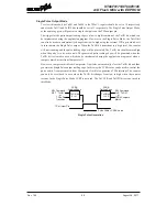
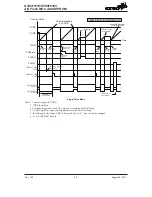
This bit is used to select the method which clears the counter. Remember that the
Standard TM contains two comparators, Comparator A and Comparator P, either of
which can be selected to clear the internal counter. With the TnCCLR bit set high,
the counter will be cleared when a compare match occurs from the Comparator A.
When the bit is low, the counter will be cleared when a compare match occurs from
the Comparator P or with a counter overflow. A counter overflow clearing method can
only be implemented if the CCRP bits are all cleared to zero. The TnCCLR bit is not
used in the PWM Output, Single Pulse Output or Capture Input Mode.


