


Rev. 1.50
5�
����st ��� �01�
Rev. 1.50
53
����st ��� �01�
HT66F0175/HT66F0185
A/D Flash MCU with EEPROM
HT66F0175/HT66F0185
A/D Flash MCU with EEPROM
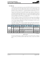
Entering the SLEEP1 Mode
There is only one way for the devices to enter the SLEEP1 Mode and that is to execute the “HALT”
instruction in the application program with the IDLEN bit in the SMOD register equal to “0” and the
WDT on. When this instruction is executed under the conditions described above, the following will
occur:
• The system clock and Time Base clock will be stopped and the application program will stop at
the "HALT" instruction, but the WDT will remain with the clock source coming from the f
SUB
clock.
• The Data Memory contents and registers will maintain their present condition.
• The WDT will be cleared and resume counting if the WDT function is enabled.
• The I/O ports will maintain their present conditions.
• In the status register, the Power Down flag PDF will be set, and WDT timeout flag TO will be
cleared.
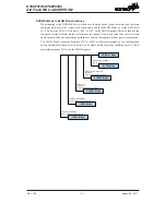
Entering the IDLE0 Mode
There is only one way for the devices to enter the IDLE0 Mode and that is to execute the “HALT”
instruction in the application program with the IDLEN bit in the SMOD register equal to “1” and
the FSYSON bit in the CTRL register equal to “0”. When this instruction is executed under the
conditions described above, the following will occur:
• The system clock will be stopped and the application program will stop at the “HALT”
instruction, but the f
TBC
and f
SUB
clocks will be on.
• The Data Memory contents and registers will maintain their present condition.
• The WDT will be cleared and resume counting if the WDT function is enabled.
• The I/O ports will maintain their present conditions.
• In the status register, the Power Down flag PDF will be set, and WDT timeout flag TO will be
cleared.
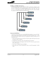
Entering the IDLE1 Mode
There is only one way for the devices to enter the IDLE1 Mode and that is to execute the “HALT”
instruction in the application program with the IDLEN bit in the SMOD register equal to “1” and
the FSYSON bit in the CTRL register equal to “1”. When this instruction is executed under the
conditions described above, the following will occur:
• The system clock, f
TBC
and f
SUB
clocks will be on but the application program will stop at the
“HALT” instruction.
• The Data Memory contents and registers will maintain their present condition.
• The WDT will be cleared and resume counting if the WDT function is enabled.
• The I/O ports will maintain their present conditions.
• In the status register, the Power Down flag PDF will be set, and WDT timeout flag TO will be
cleared.


