28
Chapter 3: Description of device
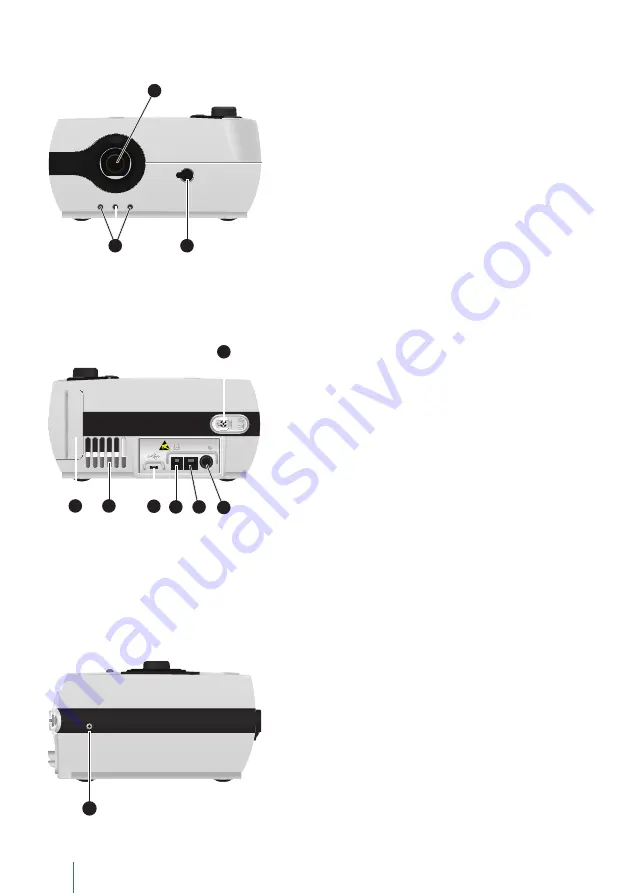
Front side of device
FiO
2
FiO
2
3
2
1
1
Connection leakage tube circuit/
humidifier
2
Connection FiO
2
sensor cable
3
Contact socket for integrable humid-
ifier AquaTREND uni
Figure 2:
Front side of device
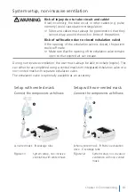
Rear of device
COM
DC
COM
DC
7
6
5
4
3
2
1
1
Oxygen connection
2
DC connection
The DC plug is connected here.
See also page 35.
3
RS232 interface (service interface)
4
Connection of remote alarm/nurse call
Only relevant for clinical use.
5. Micro-USB connection (PC connec-
tion/service interface)
Figure 3:
Rear of device
6
Ventilation slots
7
Filter cassette (coarse and fine filter)
(For information on exchange, see
page 80.)
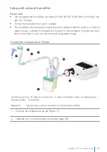
Left side of device
1
1
Oxygen output
Outlet for excessive oxygen when ven-
tilation is off
Figure 4:
Left device side
Summary of Contents for LAVI
Page 2: ......
Page 18: ...18 Chapter 1 Introduction ...
Page 26: ...26 Chapter 2 Safety warnings ...
Page 27: ...Chapter 3 Description of device 27 Chapter 3 Description of Device ...
Page 33: ...Chapter 3 Description of device 33 Chapter 4 Commissioning ...
Page 51: ...Chapter 5 Device operation 51 Chapter 5 Operating the Device ...
Page 75: ...Chapter 6 Alarms and messages 75 Chapter 7 Cleaning and Exchange of Components ...
Page 81: ...Chapter 8 Routine checks and maintenance work 81 Chapter 8 Routine Tests and Maintenance Work ...
Page 84: ...84 Chapter 8 Routine checks and maintenance work ...
Page 85: ...Chapter 9 Appendix 85 Chapter 9 Annex ...
Page 98: ...98 Chapter 9 Appendix ...
Page 99: ...Chapter 9 Appendix 99 ...
Page 100: ...100 Chapter 9 Appendix ...
Page 101: ...Chapter 9 Appendix 101 ...
Page 102: ...102 Chapter 9 Appendix ...


