


HOBO TidbiT MX Temp 400 (MX2203) and Temp 5000 (MX2204) Logger Manual
1-508-759-9500 (U.S. and International) 2
www.onsetcomp.com
1-800-LOGGERS (U.S. only)
Specifications (continued)
Full Memory Download
Time
Approximately 45 seconds; may take longer the farther the device is
from the logger.
Wetted Materials
MX2203: Polypropylene case, Delrin® battery cover, EPDM O-ring,
stainless steel screws, Santoprene® (TPE) boot
MX2204: Epoxy case, Santoprene (TPE) boot
Dimensions
MX2203: 4.45 x 7.32 x 3.58 cm (1.75 x 2.88 x 1.41 inches)
MX2204: 4.06 x 6.99 x 3.51 cm (1.6 x 2.75 x 1.38 inches)
Weight
MX2203: 36.2 g (1.28 oz)
MX2204: 32.8 g (1.16 oz)
Environmental Rating
IP68
The CE Marking identifies this product as complying with all relevant
directives in the European Union (EU).
See last page
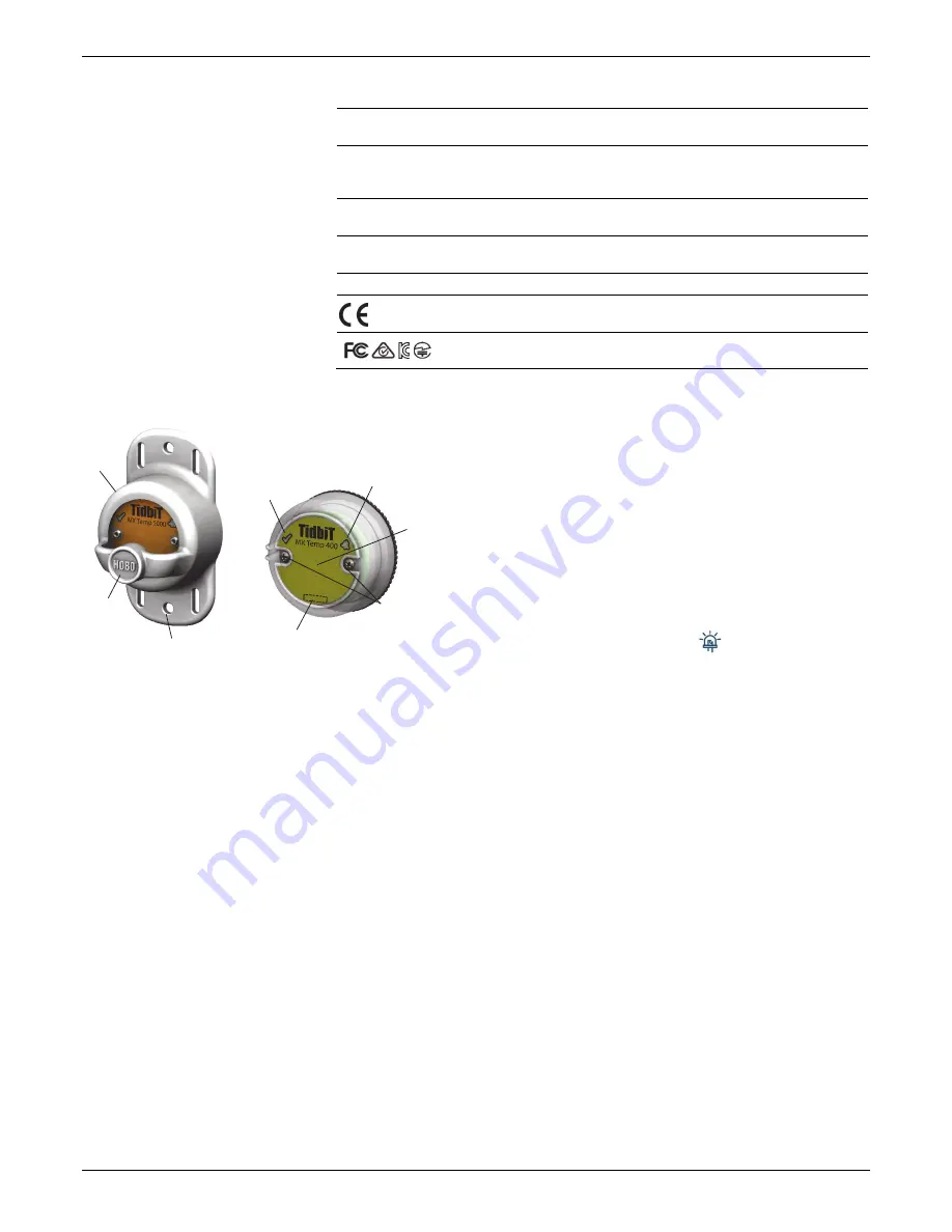
Logger Components and Operation
MX2204 MX2203
Protective Boot:
This waterproof cover protects the logger
during deployment. It has two mounting tabs and a built-in
magnet to use with the logger’s internal reed switch (see
Deploying and Mounting the Logger
).
Magnetic Start Button:
This button is functional when the
logger is inside the protective boot. Press this button for 3
seconds to start or stop the logger when it is configured to start
or stop On Button Push (see
Configuring the Logger
). Press this
button for 1 second to wake up the logger (if configured with
Bluetooth Always Off as described in
Configuring the Logger
).
You may need to press the button a second time to wake up
the logger if it is logging every 5 seconds or faster and the
temperature is -10°C (14°F) or below.
Mounting Tab:
Use the tabs at the top and bottom of the
logger to mount it (see
Deploying and Mounting the Logger
).
Reed Switch:
The logger has an internal reed switch
represented by the dotted rectangle on the logger. The reed
switch is used in conjunction with the magnetic button in the
protective boot. When the logger is removed from the boot, a
magnet placed over the reed switch can substitute for the built-
in button (see
Deploying and Mounting the Logger
).
Water Detection Screws:
These two screws can detect the
presence of water. This allows you to configure the logger in
power-saving mode in which Bluetooth advertising is active
only when the logger is removed from water. See
Configuring
the Logger
for details.
Note:
The logger checks for the presence
of water every 15 seconds when the Bluetooth Off Water
Detect power-saving mode is selected.
Temperature Sensor:
The internal temperature sensor (not
visible in the diagram) is located on upper right side of the
logger.
Status LED:
This LED blinks green every 4 seconds when the
logger is logging (unless Show LED is disabled as described in
Configuring the Logger
). If the logger is waiting to start logging
because it was configured to start On Button Push or with a
delayed start, it blinks green every 8 seconds. Both this LED and
the Alarm LED blink once when you press the button to wake
up the logger or blink four times when you press the button to
start or stop logging. If you select
in the app, both LEDs
are illuminated for 5 seconds (see
Getting Started
for more
details).
Alarm LED:
This LED blinks red every 4 seconds when an alarm
is tripped (unless Show LED is disabled as described in
Configuring the Logger
).
Getting Started
Install the HOBOconnect app to connect to and work with the
logger.
1.
Download HOBOconnect to a phone or tablet from the App
Store® or Google Play™.
Download the app to a Windows computer from
www.onsetcomp.com/products/software/hoboconnect.
2.
Open the app and enable Bluetooth in the device settings if
prompted.
3.
If this is the first time you are using the logger, firmly press
the magnetic start HOBO button near the center of the
logger to wake it up. The alarm and status LEDs blink once
when the logger wakes up. This also brings the logger to the
top of the list if you are working with multiple loggers.
4.
Tap Devices and then tap the logger tile in the app to
connect to it.
Magnetic
Start Button
Mounting Tab
Protective
Boot
Status LED
Water-Detection
Screws
Reed Switch (Internal)
Alarm LED
Temperature
Sensor
(Internal)


