HOBO MicroRX Station for HOBOnet (RX2105 and RX2106) Manual
1-800-LOGGERS
13
www.onsetcomp.com
1.
Click Devices and then RX Devices, and find the station you
want to configure. Click the arrow next to on the
Devices page and select Readout Configuration.
2.
Set the connection interval. The minimum connection
interval depends on your communication plan.
3.
If you wish to set up a second connection interval, select
the “Night Mode” checkbox. Select when night mode
should begin and end and then enter the connection
interval you want to use during that part of the day.
4.
Click Save. The changes to the connection interval will take
place the next time the station connects to HOBOlink.
You can also connect to HOBOlink from the station at any time,
regardless of the connection schedule. Press the Connect
button on the station to connect to HOBOlink. Unless the
station is running on a night mode connection interval, the
normal connection schedule will then restart after the
connection is complete. For example, a station is configured to
connect hourly and the last connection on its regular schedule
occurred at 10:05. If you use the Connect button on the station
to connect to HOBOlink at 10:15, the next connection will then
be about 11:15 based on the one-hour connection interval.
Similarly, if a station misses a connection, the connection
schedule will shift depending on the time of the next successful
connection. While the station is using a second, night mode
schedule, all connections will follow that schedule only; any
extra connections while the station is in night mode will not
cause a shift in the connection schedule.
Also note that the station will connect to HOBOlink when the
device is powered up and when you press the Start button.
Note:
All connections to HOBOlink count toward your
communications plan. If the station is nearing its limit for
monthly cell use, minimize unscheduled connections. This
includes any connections for alarms or changes you make to
the connection schedule. You can also increase the connection
interval to reduce the number of connections to HOBOlink per
day. Go to the Device Information section on your station page
in HOBOlink to check the status of the monthly
communications plan usage for the station.
Deployment Guidelines
Follow the guidelines and steps in this section for deploying and
mounting the station.
Guidelines for Deploying the Station
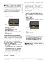
•
Check the signal strength on the LCD in the location you
wish to deploy the station to make sure it will be able to
reliably connect to HOBOlink. The station may have
difficulty connecting if there is only one bar illuminated in
the signal strength icon on the LCD. (The signal strength
shown on the LCD is from the last connection.)
•
The station must be mounted at least one foot from all
sensors to avoid interference from the built-in radio
module and antenna with the measurements made by the
sensors.
•
Make sure the station remains in a vertical position once it
is placed in its deployment location to prevent pooling of
water on the cable entries. In addition, if it is mounted
horizontally, the battery could be damaged over time in
RX2106 models as it is charged and the antenna in both
models will not have optimal range.
•
If possible, avoid sites immediately adjacent to
radio/television/microwave towers and equipment. In rare
situations, strong electromagnetic interference may result
in sensor network errors.
•
If you are using a wind speed/direction sensor or if the
station will be installed on a roof or in a location with
exposure to lightning, use a grounding wire (CABLE-
MICRO-G). A grounding wire may also reduce potential
sensor errors that can result from installing near other
radio or electrical equipment or antennas. See
Installing
the Grounding Wire
. Also, ground the tripod or mast using
appropriate grounding, such as the Grounding Kit (M-
GKA).
•
Take note of the mounting considerations in the sensor
manuals at www.onsetcomp.com/support/manuals for
additional guidelines for the sensors you are using.
•
Make sure all cables and wires are fastened securely and
routed through the cable channel. Any empty holes in the
cable channels need to be filled with the integrated plugs
to ensure the station is weatherproof if installed outdoors
or to protect it from harsh indoor environments (see the
diagrams in
Installing the Cable Channel
for how to insert
the plugs).
•
When using the AC adapter (P-AC-1) with the cable
channel installed in the RX2105 station, route the AC
adapter cable through the far-left hole in the cable
channel. Tuck the cable into the left side of the hole and
use the integrated cable channel plug in the same hole
(see the diagrams in
Installing the Cable Channel
for how
to insert the plug). The far-left hole is slightly bigger than
most other holes in the cable channel and can
accommodate both the AC adapter cable and the
integrated plug at the same time.
•
Do not store excess sensor cable wire coiled inside the
station case or within one foot outside the case.
•
Protect cables and wires with conduit. Exposed cables can
be chewed by rodents.
•
Make sure the total cable length for all installed smart
sensors does not exceed 100 m (328 ft).
•
Consider using a padlock to restrict access to the station.
With the station door closed, hook a padlock through one
of the latches on the right side of the door and lock it.
•
The RX2106 station has a built-in solar panel to recharge
the NiMH battery pack. Connect the solar panel cable to
keep the battery charged. When mounting the station,
position the solar panel in the direction where it will
receive the most sunlight through the day and throughout
each season. It may be necessary to periodically adjust the
station position as the path of sunlight changes
throughout the year or if the tree and leaf growth alters
the amount of sunlight reaching the solar panel.
•
If the location where you want to install the RX2106
station does not produce enough sunlight to charge the
battery, use an external solar panel (SOLAR-xW).
Disconnect the built-in solar panel cable and tuck it in the
station door. Plug in an external solar panel. Lightly coat
the portion of the cable that will be placed in the cable


