background image

Even the edges

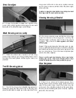
D 5. Using a bar sander or similar tool, sand the wing
roots so they will fit together with no gaps. Do not sand
too much or the dihedral angle could change.

Mark the wing servo cavity

D 6. Mark the aileron servo location on both wing
panels using a felt-tip pen. Using a hobby knife, cut an

opening into both panels following the lines you

just drew.

wing joiner will not fit in the cavity, lightly sand any

excess epoxy or uneven surfaces from the joiner edges,
sides and ends.

Caution: A snug fit is desirable between the joiner and
the wing cavity. Do not sand excessively.

Viewing the wing dihedral

D 8. Pay close attention to the orientation of the wing

joiner in relation to the wing panel, creating the

dihedral angle as shown. Test fit the wing panels
together. They should fit flush against each other

without gaps.

Note! When performing the following steps, be sure

to use a sufficient amount of epoxy to form a complete
and solid bond between the plywood wing joiner and
the two wing halves. This is the most important glue

joint in the entire airplane.

Please read through the following three steps before
mixing any epoxy. You must complete these steps
within 20 minutes from the time you mix the epoxy.

Glue the joiner

Test fit the wing joiner

D 7. Test fit the wing joiner in both wing panels by
sliding the joiner into the joiner cavity in the wing. The

joiner should slide in snugly up to the centerline. If the

D 9. Mix 3/4 oz. (22ml) of 30-minute epoxy. Use a
mixing stick or epoxy brush to apply epoxy to all four
sides of the joiner cavity. Insert the joiner into the
cavity up to the centerline marked on the joiner plate.
Be sure you are installing the joiner correctly. Quickly
proceed to the next step.

7

Summary of Contents for BrightStar 40 AWARF

Page 1: ...cklymake a successful step up to flyinglow wings withyour BrightStar40AWARE Its 90 prebuilt construction gets you out of the workshop and onto the flight line in only a matter of hours Then you can be...

Page 2: ...e pushrods 2 57 Pushrod guide tubes 2 59 6 x 3 4 sheet metal screw 4 Tail Assembly Please take your time and read through the instruction manual before starting to build your new airplane If you have...

Page 3: ...ches shown are not actual size or to scale Inch Scale Fuselage Parts Part Quantity 3 Fuselage 1 8 Wing mounting dowel 2 20 Servo tray 1 40 Stabilizer mounting base l 51 Spinner 1 52 Servo tray support...

Page 4: ...991 legal 4 channel aircraft radio system with four standard servos Many 4 channel radios include just three You may need to purchase the fourth separately Hobbico Command servos are available singula...

Page 5: ...wner of this model discover a defect in parts or workmanship within 90 days of purchase Hobbico will repair or replace it at the option of our authorized U S repair facility Hobby Services without cha...

Page 6: ...e the V shaped joiners in the same orientation as they will be glued together Sand off any bumps from the edges Draw a centerline on two of the joiners as shown D 3 Excess epoxy will squeeze out of th...

Page 7: ...els together They should fit flush against each other without gaps Note When performing the following steps be sure to use a sufficient amount of epoxy to form a complete and solid bond between the pl...

Page 8: ...toothed file until a proper fit is achieved The plywood tray should not actually contact the the sides of the servo Leave a 1 64 gap all the way around Remove the servo The servo should not touch any...

Page 9: ...ble the pushrods Apply 5 drops ofthin CA onto each hinge NOTE Do not use CA accelerator as the CA must wick into the slot Use a paper towel to absorb any excess glue Wait a few minutes for the glue to...

Page 10: ...This will fuelproof and add strength to the wood From the inside of the fuselage apply more epoxy around the dowels where they meet the sides of the fuselage These wing dowels will be used as anchors...

Page 11: ...the fuselage with a paper towel and alcohol Remove the tail post D 6 The balsa tail post is located at the rear of the fuselage behind the horizontal stabilizer slot This post was left for manufactur...

Page 12: ...Mark the stabilizer location Align the stabilizer with the wing DO NOT USE GLUE IN THIS STEP D 10 Insert the stabilizer into the horizontal stabilizer slot so it is centered in the fuselage A Place th...

Page 13: ...es Trim any of the excess decal so that it doesn t hang from the bottom of the filler Carefully trim away the covering from the fuselage where the filer will be positioned Glue the filler in place usi...

Page 14: ...s into the holes If they will not go in easily enlarge the two holes using an 11 64 drill bit Next use the drill bit or hobby knife to bevel the inside corners of the holes so that the bend in the wir...

Page 15: ...aler Trim the steering arm Drill the steering pushrod exit hole D 26 Drill a 5 32 hole through the firewall 5 16 from the bottom and 5 8 from the inside edge of the fuselage side D 29 Locate the black...

Page 16: ...luminum tube through the black rubber stopper the third aluminum tube will not be used Place the two white plastic disks over the tubes The larger disk should go towards the outside The nub on the sma...

Page 17: ...sure the foam collar is seated well against the firewall Attach fuel tubing to the tank D 39 Cut two 6 pieces of medium silicone fuel tubing not included Slide one piece onto each of the aluminum tub...

Page 18: ...bit to get into when installing props onto model airplanes If the engine quits during flight the prop will stop horizontally therefore reducing the chance of prop breakage if you are forced to land on...

Page 19: ...lug a servo extension into the aileron channel of the receiver Finally plug the switch into the receiver Wrap the receiver and battery pack in foam rubber HCAQ1050 using rubber bands or masking tape t...

Page 20: ...the two clevises to the control horns as shown Use the second hole from the outside for the elevator and the third hole from the outside hole for the rudder Check to make certain that the pushrods do...

Page 21: ...its neutral position and mark the rudder pushrod wire in the same manner Cut the pushrods D 62 Cut off the pushrods approximately 3 8 past the marks Removing the pushrods will make this and the next s...

Page 22: ...drill bit drill a hole centered approximately 3 4 behind the wing saddle on top of the fuselage Cut a 1 2 long piece of medium fuel tubing and center it inside this hole Connect the throttle servo D 6...

Page 23: ...wo 2 x 8mm wood screws Attach the wing D 74 Connect the aileron servo to the aileron extension Attach the wing onto the fuselage using 12 64 rubber bands Install 3 on each side first from front to bac...

Page 24: ...re control movement you should move the clevis to a hole closer to the control surface or you can install a larger servo wheel and move the rod at the servo end further out from center If you have too...

Page 25: ...or landing Moving the balance aft makes the model more agile with a lighter snappier feel In any case please start at the location we recommend and do not at any time balance your model outside of the...

Page 26: ...liar with the operation of R C models ask an experienced modeler to check to see that you have the radio installed correctly and that all the control surfaces do what they are supposed to The engine o...

Page 27: ...or repaired model 2 I will not fly my model aircraft in the presence of spectators until I become a qualified flyer unless assisted by an experienced helper 3 I will perform my initial turn after tak...

Page 28: ...he aircraft at a constant altitude to stop turning apply opposite aileron or rudder to level the wings then release the sticks The most common mistake when learning to fly is over control Think of pre...

Reviews: