NOTE: This section is VERY important and must
NOT be omitted! A model that is not properly
balanced will be unstable and possibly unflyable.
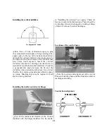
Q Use a felt tip pen or a narrow strip of tape to
accurately mark the balance point on the bottom of
the wing near both sides of the fuselage. The
balance point (CG) on the Avistar 40 is located
3-1/4" (83mm) back from the leading edge. This is
the point at which your model should balance for
your first flights. Later, you may experiment by
shifting the balance up to 5/16" (8mm) forward or
back to change the flying characteristics. Moving
the balance forward may improve the smoothness
and arrow-like tracking, but it may require more
speed for takeoff and make it more difficult to slow
down for landing. Moving the balance aft makes the
model more agile with a lighter and snappier feel.
Please start at the location we recommend and do
not at any time balance your model outside the
recommended range.
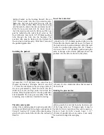
Plug the aileron servo into the receiver. Mount the
wing to the fuselage with #64 rubber bands. The
engine, muffler, propeller and fuel tank should also
be mounted for the C.G. check.
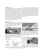
With the fuel tank empty and the wing attached to
the fuselage, lift the model with your finger tips at
the balance point. If the tail drops when you lift,
the model is "tail heavy" and you must move the
battery and/or the receiver toward the nose to
achieve balance. If the nose drops, it's "nose heavy"
and you must move the battery and/or receiver
toward the tail to achieve balance. The C.G. is
always determined with the fuel tank empty.
Balance the model by shifting the receiver battery
and receiver, then test again. When balance is
obtained note the position of the of the receiver,
and the battery pack. If the balance cannot be
achieved by positioning the battery and receiver,
you may add stick-on lead weight to the tail or
nose if required.
Confirm that the battery and receiver are securely
wrapped in foam and secured so they cannot shift
during flight or a rough landing.
IMPORTANT: After the model is 100% complete,
recheck the balance.
IMPORTANT: Go back and check your installation.
Be sure that all servo screws, horns and other
components are secure. Confirm that you have
installed the retainers on the screw lock connectors.
Apply a strip of 1/16" (1.5mm) thick foam wing-
seating tape (not included) to the wing saddle.
This tape provides a seal against dirt and exhaust
oil and cushions the wing from vibration.
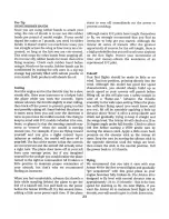
4-CHANNEL RADIO SETUP
(STANDARD MODE 2)
ELEVATOR MOVES UP
RIGHT AILERON MOVES UP
LEFT AILERON MOVES DOWN
RUDDER MOVES RIGHT
CARBURETOR WIDE OPEN
Q Check the direction of all control functions. They
must all move in the direction shown in the sketch.
If not, change the position of the reversing
switches on your transmitter.
3-1/4" (83mm)
19


