Installing the switch
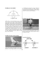
Q Cut a rectangular switch hole in the side of the
fuselage opposite the exhaust using a hobby knife.
Locate the receiver switch harness in the radio
system and remove the face plate. Place the switch
into the hole with the switch facing outward. Put
the face plate over the switch and mark the screw
holes with a felt-tip marker using the plate as a
template. Drill the screw mounting holes using a
1/16" (1.5mm) drill bit. Install the switch from the
inside of the fuselage with the "on" position toward
the rear of the plane. If the switch should get hit
while the plane is moving forward, it would not
turn the receiver off. Secure the switch using the
two screws supplied with the switch.
Preparing the servos
Q Remove the servo arms and wheels from the three
servos. Install the rubber grommets that came with
the radio system onto the servos, following the
instructions included with your radio system.
Servo installation
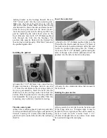
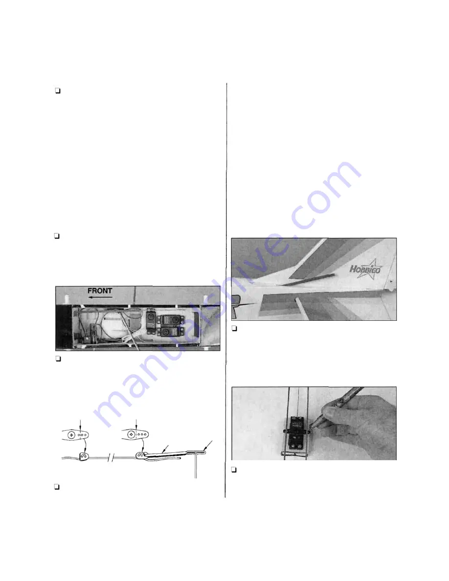
1-1 Install the three servos from your radio system as
shown in the photo. Refer to the radio manufacturer's
manual for more detailed instructions. Notice the
location and orientation of each servo as well as the
switch location.
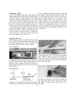
Antenna Routing
STRAIN RELIEF
INSIDE FUSELAGE
ANTENNA HOLDER
AT THE TOP OF THE
VERTICAL STABILIZER
CUT
CUT
RUBBER
BAND
Q Drill a 1/16" (1.5mm) exit hole in the center of the
rear window 1" (25.4mm) down from the edge of the
radio compartment. Route the antenna under the
plywood servo tray and up through the exit hole. Do
not cut the antenna wire. The receiver is tuned to a
specific length of antenna. Use a medium T-pin to
attach a rubber band to the top portion of the
vertical stabilizer. Tie the antenna to the rubber
band using tension to keep the antenna tight. Use
caution not to damage the antenna. A servo horn
can be cut and used to hold the antenna in place at
both ends with less likelihood of damage to the
antenna wire.
Q Locate the two 21-3/4" (555mm) outer pushrod
tubes. Slide the tubes into the fuselage from the
elevator and rudder pushrod exits. Enlarge the
exits to allow the tubes to slide in easily. Don't glue
the tubes at this time.
Q Center the ailerons, then mark the pushrods at
the point where they meet the holes in the servo
arm. Make a 90 degree bend down in the wires at
this mark.
T-PIN
17


