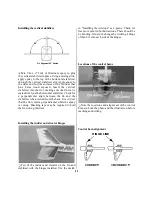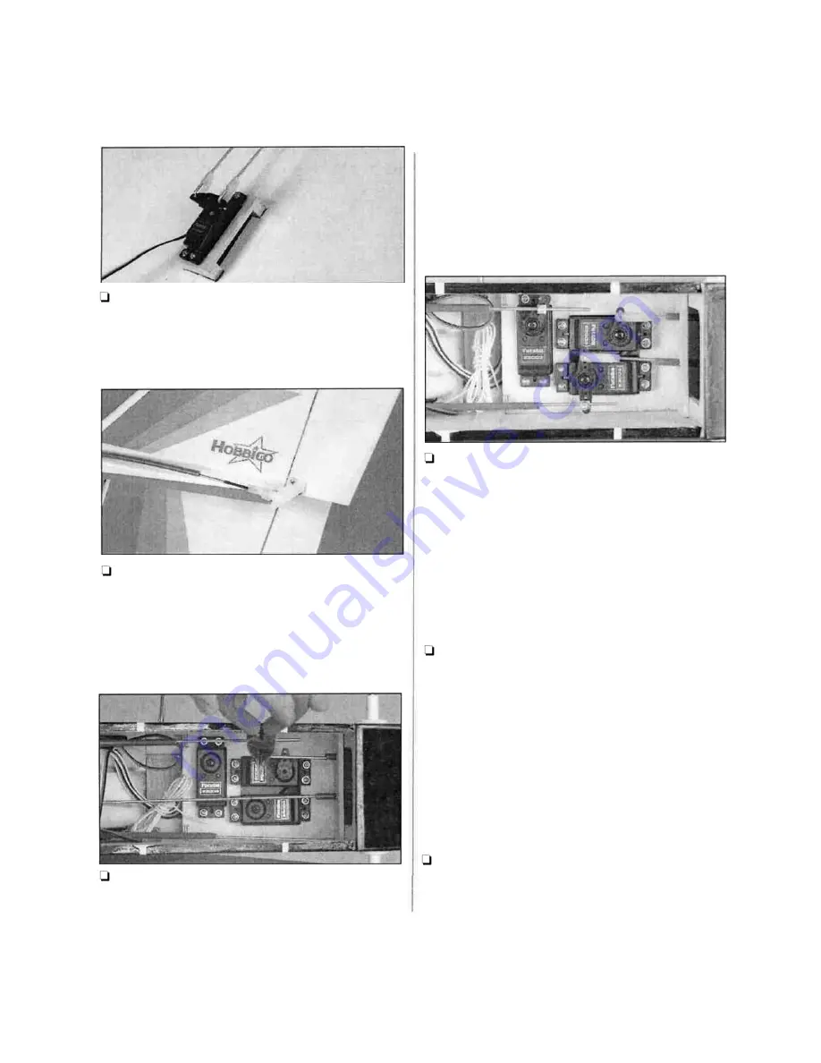
Q Cut off the excess wire 3/8" (9.5mm) above the
bend. Enlarge the servo horn holes with a 5/64"
(2mm) drill bit. Insert the bent wire pushrods into
the servo horn from the upper side, then secure
them with Nylon FasLink Pushrod Keepers.
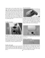
Q Thread clevises onto the 26-3/4" (680mm)
pushrods using the same technique as the aileron
pushrods. Insert the pushrods into the rudder and
elevator pushrod tubes as shown in the photo.
Attach the clevises for both the elevator and rudder
to the control horns as shown. (Both clevises are
attached in the same locations.)
Q
0 Center the elevator, then mark the pushrod
where it crosses the servo horn hole. Enlarge the
servo horn hole with a 5/64" (2mm) drill bit. Make
a 90 degree bend in the pushrod at the mark (you
may want to disconnect the clevis from the elevator
control horn to pull the pushrod wire out of the
fuselage to make it easier to bend). Cut off the
excess wire 3/8" (9.5mm) above the bend. Insert the
bent wire through the enlarged hole in the servo
horn. Secure it in place with a nylon FasLink.
Q Repeat the above step for the rudder pushrod.
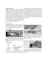
1-1 Adjust the height of the pushrod support so the
pushrods can move freely without binding. Glue the
brace into position using medium CA. Slide the
pushrod tubes so 1/8" (3mm) extends forward of
the pushrod support. Glue the pushrod tubes to the
brace using thin CA. Be very careful not to get CA
into the tubes and accidentally glue the pushrod
wires to the tubes. Glue the pushrod tubes to the
fuselage using medium CA.
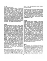
l-l With the radio on, move the throttle trim lever
and control stick to the closed position, by pulling
them back (or downward) all the way. Manually
close the throttle on the carburetor completely.
Tighten the set screw on the pushrod connector.
Check throttle operation with the radio and make
adjustments to the linkage as necessary for smooth
operation from fully closed to fully open. Use the
appropriate holes in the servo horn and throttle
arm to provide the correct amount of throttle
movement and to prevent the servo from binding
at its end points.
Q Install the nose wheel using the same technique
as the main wheels. Center the nose wheel and
tighten the screw on the pushrod connector for the
nose wheel steering.
18


