Configuration
15
iPC-I 320 Manual, Version 2.8
3.2 Design of the CAN Plugs
One (common) or two isolated high-speed bus transceivers according to ISO/IS
11898 may be present on the interface. The signals of the first bus transceiver
connect with the 9-pin sub-D-pin/bush CON2/3. With the PC/104 version the
signals are available via the pin board JP36. If two isolated bus transceivers are
assembled, the signals for the CAN bus of the second bus transceiver connect
with the header JP34. With the PC/104 version a second CAN circuit is available
as plug-in circuit board. Both bus transceivers can be electrically isolated from
the CAN bus as an option.
A version without bus transceiver is available on the interface as a further option.
In this case the signals are led out onto two pin boards each (JP14/JP15 for the
first CAN circuit, JP24/JP25 for second CAN circuit). This enables alternative
bus transceivers to be implemented.
A CAN protective circuit, consisting of a special CAN coil is also available as an
option. The circuit suppresses faults and short spikes on the CAN lines.
3.3 Pin Assignment
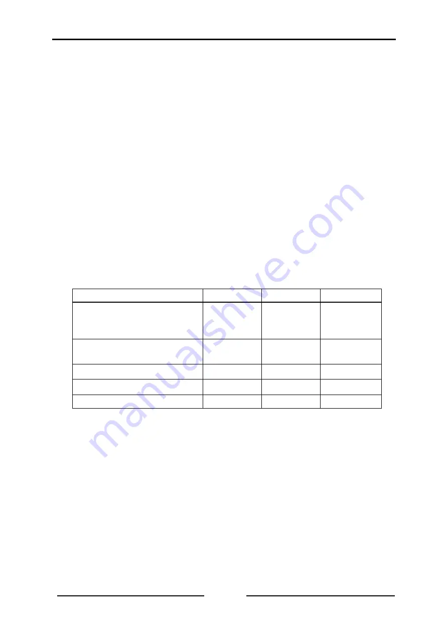
The following plugs are on the interface:
Plug
ISA slot
PC/104
AT/ISA96
CAN1
CON2,
CON3
JP14, JP15
JP36
JP14, JP15
CON2,
CON3
JP14, JP15
CAN2 (isolated from CAN1)
JP34 or
JP24, JP25
-
JP34 or
JP24, JP25
1. RS232 interface (optional)
JP17
JP17
JP17
2. RS232 interface (optional)
JP18
-
JP18
PC bus
CON1
J1 + J2
CON1
Summary of Contents for Ixxat iPC-I 320
Page 1: ...iPC I 320 Intelligent PC CAN Interface HARDWARE MANUAL ENGLISH...
Page 6: ...Introduction 6 iPC I 320 Manual Version 2 8 1 3 Block Diagram...
Page 9: ...Configuration 9 iPC I 320 Manual Version 2 8 Fig 3 2 iPC I 320 interface for ISA slot bus...
Page 10: ...Configuration 10 iPC I 320 Manual Version 2 8 Fig 3 3 iPC I 320 AT ISA96 interface...


