2-28
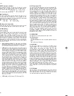
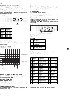
5.3 Adjustment of the audio linear playback
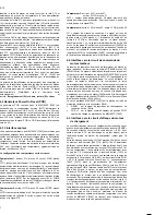
amplitude [IIC-bus]:
Purpose: To set audio part amplification LA71595 [7004-A]
Symptom, if incorrectly set:
Playback sounds too low or too loud.
– Enter the service test program and, whilst step display is
flashing, enter the step number 62, using the numerical keys.
By pressing the SELECT button whilst step 62 is flashing, the output
select is switched to Mono and the display shows, for instance:
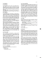
– Make a recording of the audio signal on E1.
– Connect the millivoltmeter to Scart1 Pin1(Audio out) and play
the recording back.
– The level on Scart 1, Pin1 (Audio out) can be adjusted to the set
value by pressing the UP (value increases) or DOWN keys
(value decreases).
(The amplitude changes by 1 dB each time the key is pressed).
The range is shown in the display by the numbers 0...31.
– The value is automatically stored in the EE-PROM
each time the button is pressed.
6. Display Control (AIO2)
Service tasks after replacement of the clock quartz [1170] or the
EEPROM:
6.1 Clock frequency output
Purpose: Setting the exact clock function.
Symptom, if incorrectly set:
The clock is too fast or too slow.
Remove the Motherboard from the frame and bring it into the service
position.
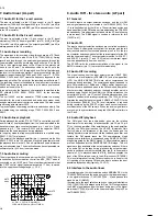
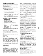
Enter the service test program and, whilst step display is flashing,
enter the step number 99, using the numerical keys.
After entering with SELECT, the display is switched off and the
watch symbol is flashing, no further function can be carried out. At
the CLOCK ADJUST measuring point [7899-A, pin 71], the
uncorrected clock frequency of approx. 8192 Hz is always output.
Measure the output frequency with the calibrated counter (minimum
resolution of 6 digits) and note down the value (f
mess
).
Determining the deviation (in ppm):
f
mess
..... measured frequency
f
nom
........target frequency (8192,00 Hz)
Deviation
= 1x10
6
x (f
mess
- f
nom
) / f
nom
Determining the correction value for Step 53:
Correction value = Deviation / 0.763 + 128 (round off to whole
number)
The calculated correction value must be between 0 and 255
(change quartz otherwise), and must be entered in Step 53 and
saved.
This step can either be exited by performing a main power source
reset, after which the service program must be entered again or by
pressing any key on the set, before step 53 can be entered.
Example:
f
mess
=8191.97Hz f
nom
=8192.00Hz
Deviation = 1x10
6
x (8191.97 - 8192.00) / 8192.00 = -3.662
Correction value = -3.662 / 0.763 + 128 = 123.20 = 123
6.2 Inputting the clock correction
Before carrying out step 53, the correction value must be
established in step 99.
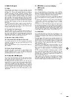
By pressing the SELECT key whilst step 53 is flashing, the display
shows, for instance (128 is the default value of an empty EEPROM):
Using the numerical keys of the remote control, the established
correction value from Step 99 is entered as a 3-digit number (value
must be between 0 and 255).
After pressing the OK key on the remote control, the entered code is
stored, the display shows OK for approx. 3 seconds and then the
stored value in decimal format.
In case of an invalid entry (value >255), the activation of the OK key
causes the content of the last stored value to be displayed and OK
does not appear in the display.
To leave the step press Select.
GB
TP
ADJ.
MODE
INPUT
500mV
RMS
±50mV
TAPE
MEAS. EQ.
SPEC.
Pin 1 of
Scart 1
(Audout)
Blank
Tape
refer to
description
SP Self-recording
and Playback,
Service mode
call up Step 62
AC Millivoltmeter,
Video Pattern,
Frequency
Generator
(Video white picture)
Audio in Scart 1,
700mV
RMS,
1kHz
TAPE
MEAS. EQ.
SPEC.
TP
ADJ.
MODE
INPUT
7899-A
pin 71
CLOCK ADJ.
Stop
Service Mode
call up Step 99
refer to description
below
Frequency counter
with 6 digits
Summary of Contents for VTFX940EUKN
Page 6: ......
Page 30: ......
Page 83: ...3 1 3 1 Wiring Diagram Motherboard ...
Page 85: ...3 3 3 3 Block Diagram Video ...
Page 87: ...3 5 3 5 Block Diagram Audio Stereo ...
Page 88: ...3 6 3 6 Supply Voltages and Bus Diagram ...
Page 91: ...3 9 3 9 Block Diagram Central Control AIO1 AIO2 OPTION ...
Page 92: ...3 10 3 10 Mother Board solder side CLOCK ADJUST 4769 ...
Page 93: ...3 11 4769 E10 ...
Page 94: ...3 12 ...
Page 119: ...THE UPDATED PARTS LIST FOR THIS MODEL IS AVAILABLE ON ESTA ...
Page 120: ......

