2-11
GB
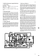
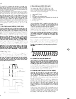
During the remainder of the scanning period, the corresponding
grid and parts of the anode are at -18V, due to the internal pull-
down resistors in the controller. This potential is still lower than the
average cathode potential of approx. -15V, prevents the
acceleration of electrons, thus causing the relevant grid and anode
segments to go dark.
The heating direct voltage of the display (U = 3.5V) is supplied from
the power supply via lines HELO or HEHI to pins F+ and F- to the
VFD display. Resistors [3070] and [3071] restrict F- to approx. -
15V.
3. Central Control AIO (AIO part)
The microcontroller (µC) TMP93CT76F [7899-B] includes the
following functions:
•
PWM outputs
•
A/D converters
•
Composite sync input
•
Special servo inputs for VCR functions
•
I²C-BUS interface
•
Shuttle evaluation
3.1 Analogue interface to the µC:
The following analogue levels are supplied to the µC’s
internal analogue/digital (A/D) converter:
•
TAE/TAS Tape End / Tape Start Detection
•
TRIV
Tracking Information Video
•
TRIA
Tracking Information Audio
•
AGC
Automatic Gain Control
•
AFC
Automatic Frequency Control
•
8SC1/2
Pin 8 Scart1 or Scart2 switching voltage
•
Key-in
Keypad evaluation
3.2 Tape end - LED control :
The LED current is switched using transistor [7804]. The ON time is
approx. 1 msec and the OFF time approx. 12 msec during playback
and 1msec to 5.5msec during the winding functions.
The LED current is typically 150 mA. In order to prevent
interference from the relatively high pulsed current ‘spreading’
through the entire unit, the LED is fed from the 14VM1, and filtered
by 2 resistors [3800, 3805] with 10R
each and a 220µF electrolytic
capacitor [2803].
3.3 CMT detection (video detection with CSYNC)
This has been extended due to identification problems with weak
transmission signals and video signals not conforming to the
STANDARD (common channel interference). The CSYNC line is
supplied to the µP [7899-B] on pin 50. A hardware integration
[7807,7808,7809] of the video pulse compensates the interference
generated by the common channels and weak signals.
3.4 EE-PROM
The EE-PROM [7818] is a non-volatile memory which can be
erased and written to electrically. (Data remains
even if the operating voltage fails). Data specific to the device such
as the X distance, head changeover position, preset stations, op-
tional bytes etc. is stored in the EE-PROM [7818].
The data is accessed by the µP via the I²C bus.
3.5 Easy link (P50)
For the communication between the TV set, video recorder and the
peripheral devices, a bi-directional single-wire bus is used, which
runs via pin 10 to scart socket 1.
The output signal is generated on pin 84 of the µC [7899-B], pin 68
is the signal input.
3.6 Shuttle:
The shuttle is connected to the motherboard on plug pos.1982. It is
a binary coded rotary switch with a rotation angle of +/- 70 degrees
and 16 switch positions. These are input and evaluated via four
lines (shuttle b1 – shuttle b4) to the input ports P24 – P27 [7899B
pins 2-5].
3.7 Satmouse
For activating a sat-receiver via an external infrared electronic
transmission unit (Satmouse) a bi-directional data line, a short-
circuit proof +5V and earth are provided via a 3-pin 3.5mm jack
[1941].
The +5V is limited to approx. 140 mA using a current limiting switch
[7812 and peripherals].
4. Deck electronics DE (DE part)
The deck interface IC MP63100FP [7463] contains the
following functional groups:
•
CTL stage (tape synchronisation)
•
Sensor interface
•
Power on reset
•
Head drum motor driver
•
Loading motor driver
•
Capstan motor control
4.1 CTL stage
The IC M63100FP [7463] contains a read/write stage for the CTL
track with the option of overwriting an existing CTL track without
any interference. The playback stage is fitted with a “digital” five-
stage AGC. This logic circuit identifies the size of the output signal
supplied by the CTL head, and then selects the best amplification
ratio in the playback stage using comparators.
The CTL head voltage can therefore vary greatly, if V
max
/ V
min
is
great. The slowest tape speed is in LP mode. The fastest speed is
adjusted during rewind. To ensure that the duty cycle in the tape
sync is always reproduced correctly in the conditions mentioned
above (important for detecting VISS marks), the amplifier must not
be overdriven.
The five-stage AGC alone cannot cover the large dynamic range of
the input voltage. The amplifier is therefore also equipped with a
low pass characteristic (fg = 3kHz typ.; internal).
Summary of Contents for VTFX940EUKN
Page 6: ......
Page 30: ......
Page 83: ...3 1 3 1 Wiring Diagram Motherboard ...
Page 85: ...3 3 3 3 Block Diagram Video ...
Page 87: ...3 5 3 5 Block Diagram Audio Stereo ...
Page 88: ...3 6 3 6 Supply Voltages and Bus Diagram ...
Page 91: ...3 9 3 9 Block Diagram Central Control AIO1 AIO2 OPTION ...
Page 92: ...3 10 3 10 Mother Board solder side CLOCK ADJUST 4769 ...
Page 93: ...3 11 4769 E10 ...
Page 94: ...3 12 ...
Page 119: ...THE UPDATED PARTS LIST FOR THIS MODEL IS AVAILABLE ON ESTA ...
Page 120: ......

