Hitachi SJ700 Series Software Instruction Manual Download Page 22

Chapter 2 Creation and Execution of a User Program 


2 - 4 

2.6 Settings on the Inverter 

The easy sequence function is a feature of the SJ700 Series Inverter. The easy sequence function 
enables the inverter to access the variables written in a user program via inverter input/output terminals. 
Programming software EzSQ provides the reserved variables for control access to the inverter via 
external terminals. You can combine these variables as required to control inverter operation. 
Some reserved variables require the inverter settings to enable the variables. Also, the settings of 
frequency commands, operation commands, and input/output terminals on the inverter must follow those 
specified in the user program. 
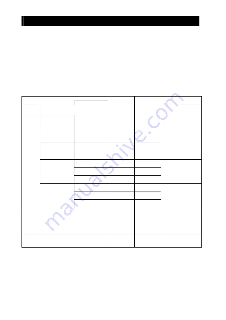
The table below lists the items, reserved variables, and function codes that must be configured when 
using the easy sequence function. For details on the reserved variables, see the explanation of settings 
related to the easy sequence function in Chapter 5. 
 

Item 

Category 

 Terminal 

name 

Variable notation 

in program 

Related function 

code 

Variable/terminal use 

condition 

Operation 
switching 

Selection of easy sequence function 

A017 

Program run signal 

PRG (FW terminal) 

A017 

The PRG terminal is 
enabled when A017 = 01. 
(The FW function is 
disabled.) 

General-purpose input 
contacts (8 contacts) 

Intelligent input 
terminals 1 to 8 

X (00) to X (07)

Xw 

C001 to C008 

Intelligent output 
terminals 11 to 15 

C021 to C025 

General-purpose 
output contacts (6 
contacts) 

Intelligent relay output 
terminals AL0 to AL2 

Y (00) to Y (05)

Yw 

C026 

Function code settings are 
required. 

O terminal 

XA (0) 

OI terminal 

XA (1) 

General-purpose 
analog inputs   
(3 terminals) 

O2 terminal 

XA (2) 

No setting is required. 

FM terminal 

YA (0) 

C027 

AM terminal 

YA (1) 

C028 

Input/ 
output 
switching 

General-purpose 
analog outputs   
(3 terminals) 

AMI terminal 

YA (2) 

C029 

Function code settings are 
required. 

Frequency source setting 

SET-Freq 

A001 

Related variables are valid 
only when A001 = 07. 

Run command source setting 

FW, RV 

STA, STP, F/R

A002 

Related variables are valid 
only when A002 = 01. 

Command 
switching 

Accel/decal time input selection 

ACCEL 
DECEL 

P031 

Related variables are valid 
only when P031 = 03. 

Other 

User-defined variables (32 variables) 

U (00) to U (31)

P100 to P131 

The variables can be 
redefined by using the 
digital operator or EzSQ. 

Summary of Contents for SJ700 Series Software

Page 1: ...HITACHI INVERTER SJ700 2 SERIES EASY SEQUENCE PROGRAMMING SOFTWARE EzSQ INSTRUCTION MANUAL Read through this Instruction Manual and keep it handy for future reference NT X HITACHI ...

Page 2: ...curring When using the inverter together with optional products also read the manuals for those products Note that this Instruction Manual and the manual for each optional product to be used should be delivered to the end user of the inverter Handling of this Instruction Manual The contents of this Instruction Manual are subject to change without prior notice Even if you lose this Instruction Manu...

Page 3: ...rcumstances Be sure to follow every safety instruction which contains important safety information Also focus on and observe the items and instructions described under Notes in the text WARNING During trial operation of the inverter with a user program a user program error may cause the motor driven by the inverter to run uncontrollably Be sure to implement safety measures such as the emergency st...

Page 4: ... 3 1 Code Description Format 3 1 3 1 1 Line 3 1 3 1 2 Label field 3 1 3 1 3 Mnemonic field 3 1 3 1 4 Parm 1 to 6 fields 3 1 3 1 5 Comment field 3 1 3 2 Data Description Format 3 2 3 2 1 Variable field 3 2 3 2 2 Define field 3 2 3 2 3 Answer field 3 2 3 2 4 Comment field 3 2 3 3 Variables and Ranges of Numerical Values 3 2 3 4 Operators 3 3 3 5 Conditions 3 3 Chapter 4 How To Use EzSQ 4 1 Starting ...

Page 5: ...rip goto statement 5 5 ifs then else end if statements 5 6 if statement 5 7 for next loop statements 5 8 while loop statement 5 9 until loop statement 5 10 select case syntax statement 5 10 call statement 5 11 inc statement 5 12 dec statement 5 12 Label definition statement 5 13 wait statement 5 13 5 3 Operators 5 14 5 4 Conditional Expressions 5 14 5 5 Input Output Control Instructions 5 15 X or ...

Page 6: ...n selection A017 6 2 6 3 Switching of Input Output Terminals 6 2 6 3 1 Program run signal input terminal PRG terminal 6 2 6 3 2 General purpose contact input terminals 6 2 6 3 3 General purpose contact output terminals 6 3 6 3 4 General purpose analog input terminal O terminal 6 3 6 3 5 General purpose analog input terminal OI terminal 6 3 6 3 6 General purpose analog input terminal O2 terminal 6 ...

Page 7: ...ned variables U 00 to U 31 P100 to P131 6 7 Chapter 7 Errors and Troubleshooting 7 1 Errors Specific to the Easy Sequence Function 7 1 7 2 Troubleshooting 7 2 Chapter 8 Appendix 8 1 Inverter Parameters and Available Settings 8 1 ...

Page 8: ...Contents vii ...

Page 9: ...Chapter 1 Introduction This chapter explains how to install EzSQ uninstall it and prepare for programming with EzSQ 1 1 Installing and Uninstalling EzSQ 1 1 1 2 Preparing for Programming 1 5 ...

Page 10: ......

Page 11: ...ns to start up the EzSQ Installer 1 Start Microsoft Explorer browse the files on the CD ROM drive and then select and open the setup exe file 2 Select Run from the Start menu of Windows Click the Browse button in the Run dialog box to open the Browse File dialog box select setup exe among the files on the CD ROM drive and then click the Open button 3 Select Run from the Start menu of Windows Enter...

Page 12: ...ing click the Next button To change the installation destination folder from the default click the Change button and then select a desired folder 5 The wizard indicates that it is ready to start installation Click the Install button 6 The wizard indicates that installation has been completed Click the Finish button to exit the wizard ...

Page 13: ... Panel Delete EzSQ by using the EzSQ InstallShield Wizard on the EzSQ Installation CD ROM To uninstall EzSQ by using the EzSQ InstallShield Wizard follow the procedure below 1 Perform installation steps 1 and 2 described above to start up the installation wizard Click the Next button as instructed in the wizard window 2 The wizard shows program maintenance options Select Remove and click the Next ...

Page 14: ... 3 The wizard requests you to confirm program deletion Click the Remove button 4 The wizard indicates that program deletion has been completed Uninstallation of EzSQ has been completed Click the Finish button to exit the wizard ...

Page 15: ...Operator connection port The following figure shows the basic system configuration for programming Install EzSQ on your Windows personal computer and connect the personal computer to the SJ700 inverter via the PC inverter connection cable After completing these preparations you can operate EzSQ to create a user program and download it to the SJ700 inverter SJ700 Inverter Commercially available Win...

Page 16: ...Chapter 1 Introduction 1 6 ...

Page 17: ...ocedures for creating and executing a user program 2 1 Language Specifications 2 1 2 2 Overview of System Configuration 2 2 2 3 General Flow of Operation and Setup 2 3 2 4 Creation of User Program 2 3 2 5 Syntax Check 2 3 2 6 Settings on the Inverter 2 4 2 7 Execution of User Program 2 5 ...

Page 18: ......

Page 19: ...AM terminal Input output related functions External output General purpose analog output YA 2 Assignable to the AMI terminal Instructions 1 Program control instructions Loop for Unconditional branching goto Conditional branching if then ifs then select case until and while Time control wait Subroutine call sub Others entry end cont inc and dec 2 Arithmetic instructions Arithmetic operation Remaind...

Page 20: ...puter The table below lists the main functions of EzSQ Function Description Programming support Supports the input editing saving reading and printing of user programs Compilation Compiles an edited user program Downloading and uploading Downloads a user program to the inverter Uploads a user program to from the inverter Debugging support Monitors program execution inverter status and others SJ700...

Page 21: ...e Window to configure the initial values for program execution Use the Monitor Window to monitor the status of program execution and inverter operation and debug a created user program After checking the program syntax and counting the program steps download the user program to the inverter For details on the above operations see Chapter 4 How To Use EzSQ 1 Code input in the Code Window A main rou...

Page 22: ...ion code Variable terminal use condition Operation switching Selection of easy sequence function A017 Program run signal PRG FW terminal A017 The PRG terminal is enabled when A017 01 The FW function is disabled General purpose input contacts 8 contacts Intelligent input terminals 1 to 8 X 00 to X 07 Xw C001 to C008 Intelligent output terminals 11 to 15 C021 to C025 General purpose output contacts ...

Page 23: ...put terminals One relay output terminal Selecting MO6 Y 05 Selecting YA0 YA 00 Selecting YA1 YA 01 Selecting YA2 YA 02 Input and output terminals available for general purpose input output settings Three analog input terminals Three analog output terminals XA 00 XA 01 XA 02 2 7 Execution of User Program After downloading the user parameters to the inverter enable the easy sequence function by sett...

Page 24: ...Chapter 2 Creation and Execution of a User Program 2 6 ...

Page 25: ...This chapter explains the syntax and definitions used for programming 3 1 Code Description Format 3 1 3 2 Data Description Format 3 2 3 3 Variables and Ranges of Numerical Values 3 2 3 4 Operators 3 3 3 5 Conditions 3 3 ...

Page 26: ......

Page 27: ...1 2 Label field Use the Label field to describe for example the branch destination for a branch instruction 3 1 3 Mnemonic field Use the Mnemonic field to describe the instruction to be executed For details on the instructions see Chapter 5 Instruction Words 3 1 4 Parm 1 to 6 fields Use the Parm 1 to 6 fields to describe the arguments required to execute an instruction Up to six arguments can be d...

Page 28: ...on result You cannot rewrite the calculation result 3 2 4 Comment field You can describe a comment about the variable described on the line 3 3 Variables and Ranges of Numerical Values The tables below show the ranges of numerical values that can be specified in the Code Window and Data Window 1 Variables and ranges of numeric values Type of variable Variable name Range of numeric values Bit and c...

Page 29: ...t variable 3 Addition Subtraction Multiplication Division Remainder Absolute value Substitution OR logical addition AND logical product XOR exclusive OR NOT negation Note 1 variable 2 can be a constant ranging from 0 to 127 Note 2 variable 3 can be a constant ranging from 2 31 to 2 31 1 3 5 Conditions You can use a conditional expression to compare two variables The operation result of a condition...

Page 30: ...Chapter 3 Syntax 3 4 ...

Page 31: ...ions 4 10 4 6 Methods of Entering Data in the Data Window 4 12 4 7 Compiling a Program 4 14 4 8 Downloading a Program to the Inverter 4 15 4 9 Saving a Program in EEPROM 4 16 4 10 Compilation and Downloading 4 16 4 11 Uploading a Program from the Inverter 4 17 4 12 Reset 4 18 4 13 Monitor Window 4 18 4 14 Printing a Program 4 19 4 15 Referencing the Help Information 4 19 4 16 Version Information 4...

Page 32: ......

Page 33: ... 1 On your personal computer from the Start menu select Programs Hitachi Industrial Equipment Systems Co Ltd EzSQProgramEditor exe to start up EzSQ 2 The EzSQ MENU window appears 3 To connect the personal computer to the inverter select the connection port to be used and click the Connection button 4 Click the Programming button The Editor window appears ...

Page 34: ...the currently edited program the following message dialog box will appear Yes Saves the currently edited program and then terminates EzSQ No Terminates EzSQ without saving the currently edited program Cancel Cancels the termination of EzSQ 3 If you have already saved the currently edited program the following message dialog box will appear Yes Terminates EzSQ No Cancels the termination of EzSQ 1 1...

Page 35: ...e program in the Code Window Set the initial values of variables in the Data Window Temporarily save the created program Compile the program Did compilation end normally Download the program to the inverter Was download completed Verify program operation Is program operation normal Save the downloaded program in EEPROM Store the created program Exit EzSQ Correct the program Correct the data Yes No...

Page 36: ...mand Ctrl N keys 2 Discard the currently edited program and then start editing a new program 2 Saving a new program as a file To save a new program follow the procedure below 1 Select Save as from the File menu Shortcut command Ctrl A keys 2 The Save as dialog box appears 3 Click the Save button to save the new program The program name you gave to the new program is used as the file name except th...

Page 37: ...he file to be opened and then click the Open button The Program Editor reads the selected program file You can select isq or csv as the file type 4 Overwriting a file 1 Select Save program from the File menu Shortcut command Ctrl S keys or the file saving icon button under the menu bar 2 The currently edited program is saved by overwriting the file having the same file name as the program name of ...

Page 38: ...Comment This field allows you to describe a comment e g a note on programming Parm 1 to Parm 6 These fields allow you to enter the parameters required for the instruction entered in the Mnemonic field Mnemonic This field allows you to enter a mnemonic instruction code or the variable to store an operation result Label This field allows you to enter a label name that indicates the corresponding lin...

Page 39: ...nserts or overwrites an instruction statement or variable in a cell selected in the Code Window Example of operation 1 In the Program Code input tab click the Struct if button 2 A structured if instruction is inserted in the cell currently selected in the Code Window 3 If you temporarily enter a descriptive statement enclosed by and in place of an instruction or parameter in a cell you must enter ...

Page 40: ...r on the keyboard 2 A pull down list appears to show the instructions that can be entered in the cell 3 If the desired instruction is not shown use the vertical scroll bar along the right edge of the list to scroll through the list 4 Select and click the instruction to be entered You can also use the arrow keys and on the keyboard to select an instruction and then press the Enter key to enter it 5...

Page 41: ...ons directly from the keyboard in selected cells 1 Click in the Mnemonic cell in which to enter an instruction 2 Type in the instruction statement from the keyboard 3 Press the Tab or arrow key 4 The Parm cell next to the cell in which you entered the instruction changes to the selected state 2 4 ...

Page 42: ...deleted 2 Select Cut from the Edit menu on the menu bar You can also execute this command by clicking the icon under the menu bar or pressing the Ctrl X keys on the keyboard 3 The selected line is deleted The deleted line can be pasted with the Paste command as described below The lines following the deleted line are shifted upward 4 Copy The Copy command copies one or more selected lines 1 Select...

Page 43: ... keys on the keyboard 2 The Find dialog box appears 3 Enter the string to be found and then click the Find button to start searching 4 Clicking the Cancel button closes the Find dialog box 5 Clicking the Replace button switches to the Replace dialog box 8 Replace The Replace command searches the selected area Code Window or Data Window to find a specified string and replace it with another specifi...

Page 44: ...alue of each variable Comment This field allows you to describe a comment e g a note on programming The entered comment will be saved when the program file is saved but will not be reflected in the program compilation result The comment will be deleted when the compiled program is uploaded after being downloaded once Answer This field displays the initial variable settings to be applied when execu...

Page 45: ...ered and the calculation result must be within the upper and lower limits set for the target variable 2 After entering expressions or values for the variables click the Calculate button 3 The Answer field shows the calculation result for each variable If the calculation expression entered for a variable references the same variable an error message appears Also the Result field for the variable in...

Page 46: ... the menu bar or pressing the Ctrl F9 keys on the keyboard 2 EzSQ compiles the program and displays a normal end message when no error is detected Then the program is ready for downloading Note If EzSQ detects an error during compilation it displays the line where the error is detected in case of an instruction format error or both the line and string where the error is detected in case of a param...

Page 47: ... transfers the program from the personal computer to the memory buffer of the inverter The program is not stored in internal memory EEPROM of the inverter After the transfer ends a dialog box appears to ask you whether to save the downloaded program in EEPROM Click the Yes button to save the downloaded program in the inverter s EEPROM Click the No button to omit saving 5 After the download process...

Page 48: ...y clicking the icon under the menu bar 2 EzSQ compiles the program and if no error is detected downloads it to the inverter successively Click the OK button in the dialog box shown below 3 After the program is downloaded transferred to the inverter a dialog box appears to ask you whether to save the downloaded program in the inverter s EEPROM Click the Yes button to save the downloaded program in ...

Page 49: ...proceed 3 Click the OK button in the Program Upload dialog box to start uploading 4 After uploading ends an end message dialog box appears Click the OK button Note 1 The source files to be searched on the personal computer by this operation are those contained in the user folder created in the same folder where EzSQ was installed On the personal computer be sure to store all source files downloade...

Page 50: ... Inverter Instruction Manual FM 1 Monitors the inverter output frequency in the same way as the output frequency monitoring function code d001 of the inverter Iout 2 Monitors the inverter output current in the same way as the output current monitoring function code d002 of the inverter Dir 3 Monitors the motor rotation direction in the same way as the rotation direction monitoring function code d0...

Page 51: ...button 6 Clicking the Options button opens the Page Setup dialog box 4 15 Referencing the Help Information You can reference the electronic data of this Instruction Manual from the Program Editor window 1 Select Help from the Help menu on the menu bar You can also execute the Help command by pressing the F1 key on the keyboard 2 The PDF file containing the electronic data of this Instruction Manua...

Page 52: ...a password appears 1 Enter a password that consists of up to eight alphanumeric characters in the Password and Password for confirmation fields 2 Click the setting button to register the password in the inverter Note You cannot clear the set password by user setting initialization on the inverter To clear the set password perform the password clearance operation described below 4 17 2 Clearing a p...

Page 53: ...1 List of Instructions 5 1 5 2 Program Control Instructions 5 4 5 3 Operators 5 14 5 4 Conditional Expressions 5 14 5 5 Input Output Control Instructions 5 15 5 6 Timer Control Instructions 5 20 5 7 Inverter Control Instructions 5 24 5 8 Other Reserved Variables 5 29 5 9 Inverter Monitor Variables 5 37 ...

Page 54: ......

Page 55: ...tement if condition then label name Branches processing to the step labeled with label name when the condition is met ifs condition Starts the structured if statement then Indicates the beginning of instructions to be executed when condition is met instruction set Indicates the instructions to be executed when condition is met else Indicates the beginning of instructions to be executed when condit...

Page 56: ... 2 constant and variable 3 constant and assigns the result to variable 1 variable 1 variable 2 constant variable 3 constant Subtracts variable 3 constant from variable 2 constant and assigns the result to variable 1 variable 1 variable 2 constant variable 3 constant Multiplies variable 2 constant by variable 3 constant and assigns the result to variable 1 Arithmetic operation variable 1 variable 2...

Page 57: ...nt elapses Delay operation delay off variable 1 TD k variable 2 constant Turns off the terminal specified by variable 1 after the time specified by variable2 constant elapses timer set TD k variable constant Sets variable constant in a specified timer and starts the timer Timer control timer off TD k Stops the specified timer variable UB ii Fetches internal user contact information and stores it i...

Page 58: ...s Instructions to start and end a subroutine Format Format Description sub subroutine name This instruction indicates the beginning of a subroutine end sub This instruction indicates the end of a subroutine Control is returned to the calling routine Explanation The sub and end sub statements indicate the beginning and end of a subroutine respectively subroutine name Specifies the name of a called ...

Page 59: ...he branch target step line Sample program goto LABEL1 Unconditionally branch to step LABEL1 LABEL1 FW 1 Branch target on trip goto statement Instruction to branch processing upon the occurrence of an event Format Format Description on trip goto label name This instruction branches processing to the step labeled with label name when the inverter trips Explanation Use this instruction to branch proc...

Page 60: ...en condition is met The instructions may be described on two or more lines The instructions are executed in units of lines in a cycle as explained below instruction set 2 Specifies the instructions to be executed when condition is met The instructions may be described on two or more lines The instructions are executed in units of lines in a cycle as explained below Processing cycle Note that condi...

Page 61: ...on Specifies a conditional expression among those listed in Section 3 5 Conditions of Chapter 3 Syntax label name Specifies the label name of the branch target step line Processing cycle Note that condition check and branch processing are executed in the same cycle Refer to the statement execution sequence indicated by parenthesized numbers in the comment fields of the sample programs below Sample...

Page 62: ...he initial value of variable to be applied at the beginning of the loop You can specify a variable name or immediate value i e a value that can be entered directly The immediate value must be an integer ranging from 0 to 127 To use a larger numerical value preset the value in a variable and specify the variable as start value end value Specifies the limit value at which to exit the loop Processing...

Page 63: ...tion 11 Processing proceeds to the following step line Sample program Sequence of execution for U 00 0 3 1 1 Y 00 1 2 5 8 Y 00 0 3 6 9 next 4 7 10 Y 00 1 11 while loop statement Instruction to conditionally execute a pre conditioned loop Format Format Description while condition instruction set wend This instruction executes instruction set while condition is met Note that condition is checked bef...

Page 64: ...le conditions Format Format Description select conditional variable case conditional value 1 instruction set 1 case conditional value 2 instruction set 2 case else instruction set n end select This instruction executes instruction set 1 to instruction set n 1 described in a case statement when conditional variable matches conditional value 1 to conditional value n 1 in the case statement respectiv...

Page 65: ...ubroutine Format Format Description call subroutine name This instruction branches processing unconditionally to the subroutine specified by subroutine name Explanation This instruction branches processing unconditionally to the subroutine specified by subroutine name After the subroutine is executed processing proceeds to the instruction that follows the calling step Sample program entry call SUB...

Page 66: ...t of U 00 to terminals Y 00 to Y 05 wait 0 5 Wait 0 5 second goto LOOP end Data area Data Window U 00 255 U 01 63 dec statement Instruction to decrement a variable Format Format Description dec variable This instruction decrements variable by 1 Explanation This instruction subtracts 1 from the value of variable Sample program Code area Code Window entry LOOP dec U 00 Assign U 00 1 to U 00 U 00 U 0...

Page 67: ...tion to make processing wait Formats Format Description 1 wait iii ii This instruction makes processing wait for iii ii seconds 2 wait condition This instruction makes processing wait until condition is met Explanation Format 1 This instruction makes processing wait for iii ii seconds After iii ii seconds elapse the next instruction is executed Format 2 This instruction makes processing wait until...

Page 68: ...AND logical product XOR exclusive OR NOT negation Note 1 variable 2 can be a constant ranging from 0 to 127 Note 2 variable 3 can be a constant ranging from 231 to 231 1 5 4 Conditional Expressions You can use the following conditional expressions as condition in instruction statements Format Description variable 1 variable 2 variable 1 variable 2 variable 1 variable 2 variable 1 variable 2 variab...

Page 69: ...of terminal active state C011 to C018 is reflected in the polarity on or off of contact inputs X 00 to X 07 and Xw When creating a user program consider the on and off states of actual intelligent input terminals 1 to 8 Note 2 Since this instruction reads the internal input terminal data at least twice in two execution cycles storing the read data in variable is delayed by at least two execution c...

Page 70: ...erminal Y 05 on Yw U 00 U 00 32 Note The setting of terminal active state C031 to C036 is reflected in the polarity on or off of contact inputs Y 00 to Y 05 and Yw when the data is output to intelligent output terminals 11 to 15 and the relay output terminal When creating a user program consider the on and off states of actual intelligent output terminals Sample programs Sample 1 Program to turn t...

Page 71: ...Chapter 5 Instruction Words 5 17 LBL2 FW 0 Wait RUN 0 Decelerate and stop the motor end Data area Data Window U 00 1000 U 01 2000 U 02 3000 U 03 4000 U 04 5000 U 05 6000 ...

Page 72: ...en LBL2 When the output frequency is less than 20 Hz if FM U 02 then LBL3 When the output frequency is less than 30 Hz if FM U 03 then LBL4 When the output frequency is less than 40 Hz if FM U 04 then LBL5 When the output frequency is less than 50 Hz if FM U 05 then LBL6 When the output frequency is less than 60 Hz if FM U 05 then LBL8 When the output frequency is 60 Hz LBL1 Yw 1 Output 1 to Yw go...

Page 73: ...eral purposes The inverter has eight general purpose contacts that are writable and readable by bit access UB 00 to UB 07 or word access UBw Details of the formats are explained below Format 1 With this format the instruction reads the status of the ii th bit of internal user contact data into variable 0 off 1 on Format 2 With this format the instruction writes variable or constant to the ii th bi...

Page 74: ...ounter TD k Timer contact one shot timer Block diagram for timer function The timer counter is a 31 bit up counter that runs in a 10 ms cycle 1 count per 10 ms and operates as a free running timer when the execution of a easy sequence program is started When the timer set delay on or delay off instruction is executed the timer counter is cleared and restarted While the timer counter is operating i...

Page 75: ... counter Then the value of timer contact variable TD k is 0 off 2 Subsequently the instructions described after the timer set instruction are executed 3 When the timer counter TC k reaches the specified count the value of timer contact variable TD k changes to 1 on only once Then the timer counter TC k stops counting Sample program FW 1 timer set TD 0 5 00 Start the 5 second timer counter wait TD ...

Page 76: ... on or delay off delay operation instruction Instruction to turn a variable on or off with a delay Formats Format Description delay on variable 1 TD k variable 3 or constant This instruction sets the count of the k th timer in variable 3 or constant and starts the timer counter When timer output TD k is turned on variable 3 is turned on delay off variable 1 TD k variable 3 or constant This instruc...

Page 77: ... 60 Hz delay off FW TD 0 15 00 Start the 15 second timer counter Turn the FW terminal off after 15 seconds elapse wait RUN 0 Wait until the motor stops delay on RV TD 0 1 00 Start reverse rotation after 1 second elapses SET Freq 1000 Accelerate the reverse rotation speed up to 10 Hz wait FM U 00 Wait until the output frequency reaches 10 Hz RV 0 Decelerate and stop the motor Wait RUN 0 Wait until ...

Page 78: ...minal specified by input terminal function is turned off on or off respectively The function and operation of the specified input terminal are the same as those that can be specified by the terminal functions C001 to C008 on the inverter For details refer to the SJ700 Series Inverter Instruction Manual Sample program Program to make the inverter alternately repeat forward acceleration and decelera...

Page 79: ...re the same as those that can be specified by the terminal function C021 to C026 on the inverter For details refer to the SJ700 Series Inverter Instruction Manual Sample program Code area Code Window SET Freq 6000 Set the output frequency to 60 Hz ACCEL 1000 Set the acceleration time to 10 seconds DECEL 1000 Set the deceleration time to 10 seconds FW 1 wait X 01 1 Wait until X 01 is turned on ACCE...

Page 80: ...ables can be used to monitor the the causes of the last six trips made by the inverter The data monitored with this variable corresponds to the data monitored by trip monitoring functions 1 to 6 d081 to d086 These variables are read only Sample program Program to display the summation of U 01 and U 02 on user monitor 2 d027 Code area Code Window Umon 02 U 01 U 02 User Trip User trip issue command ...

Page 81: ...r parameter of which the setting is to be changed The range of parameter settings depends on the standard inverter specifications For the inverter parameters and ranges of their settings refer to the SJ700 Series Inverter Instruction Manual Specify an integer as the desired new setting of the parameter in variable or constant To specify a numerical value other than 0 to 127 preset the value in a v...

Page 82: ...depends on the standard inverter specifications For the inverter parameters and ranges of their settings refer to the SJ700 Series Inverter Instruction Manual Sample program Program to check whether the inputs of frequency command and acceleration deceleration time are assigned to the easy sequence function Code area Code Window entry Yw 0 mon param A001 U 00 Assign the content of A001 to U 00 mon...

Page 83: ...iables from the digital operator The changes made from the digital operator will be stored in EEPROM Sample program U 00 U 00 U 01 U 02 U 00 U 02 U 03 U 00 mod U 01 Variable name Range of values Default Unit Data size Attribute UL 00 to UL 07 Internal user variable 231 to 2 31 1 0 Signed 2 word data Readable and writable Explanation Internal user variables are the general purpose functions that ca...

Page 84: ...e as the set frequency you must change the setting of frequency source setting A001 to 07 PRG Note 2 This variable can be read regardless of the setting of A001 The currently applied set frequency is read from this variable Sample program Program to alternately repeat forward rotation of the motor at 60 Hz and reverse rotation at 10 Hz Code area Code Window entry LOOP SET Freq 6000 Set the output ...

Page 85: ...ds FW 1 Start forward rotation of the motor LOOP if FW U 00 then LBL1 When the output frequency is less than 5 Hz set the acceleration time to 10 seconds if FM U 01 then LBL2 When the output frequency is less than 10 Hz change the acceleration time to 5 seconds if FM U 02 then LBL3 When the output frequency is less than 30 Hz change the acceleration time to 1 second if FM U 03 then LBL4 When the o...

Page 86: ...hange the deceleration time according to output frequency Code area Code Window DECEL 3000 Set the deceleration time to 30 seconds FW 0 Start deceleration of the motor wait FM U 04 Wait until the output frequency falls below 55 Hz DECEL 1000 Change the deceleration time to 10 seconds wait FM U 03 Wait until the output frequency falls below 50 Hz DECEL 500 Change the deceleration time to 5 seconds ...

Page 87: ...neral purpose analog inputs Code area Code Window FW 1 LOOP UL 00 XA 0 Fetch analog input data UL 00 UL 00 60 Convert the scale UL 00 UL 00 100 if U 00 U 00 then LBL1 When data is less than 16 67 set the output frequency to 10 Hz if U 00 U 01 then LBL2 When data is less than 33 33 set the output frequency to 20 Hz if U 00 U 02 then LBL3 When data is less than 50 00 set the output frequency to 30 H...

Page 88: ... 00 To obtain the analog outputs you must assign general purpose output functions to the FM AM and AMI terminals with inverter parameters C027 C028 and C029 YA 0 FM output terminal C027 12 YA0 YA 1 AM output terminal C028 13 YA1 YA 2 AMI output terminal C029 14 YA2 Sample program Program to output inverter output frequency data to a general purpose analog output as data that is one half of the ful...

Page 89: ...ogram Program to accelerate the motor step by step by using a free running timer Code area Code Window ACCEL 1000 Set the acceleration time to 10 seconds DECEL 1000 Set the deceleration time to 10 seconds SET Freq 0 Set the output frequency to 0 Hz LOOP FW 1 Start forward rotation of the motor if TC 5 U 00 then LBL1 When TC 5 indicates less than 10 seconds if TC 5 U 01 then LBL2 When TC 5 indicate...

Page 90: ...e TD k corresponding to the timer counter variable retains its status Sample program Program to accelerate the motor step by step by using a timer contact TDw 0 ACCEL 1000 Set the acceleration time to 10 seconds DECEL 1000 Set the deceleration time to 10 seconds SET Freq 0 Set the output frequency to 0 Hz LOOP FW 1 Start forward rotation of the motor timer set TD 5 10 00 Start the 10 second timer ...

Page 91: ... This variable is read only Sample program Program to turn a contact output on when output frequency exceeds 50 Hz and turn the contact output off when output frequency falls below 10 Hz Code area Code Window LOOP if FM U 00 then LBL1 When the output frequency is less than 10 Hz if FM U 01 then LBL2 When the output frequency is more than 50 Hz goto LBL3 LBL1 UB 02 0 Turn UB 02 off goto LBL3 LBL2 U...

Page 92: ... When output current is 100 or less change the acceleration time to 5 seconds if U 10 U 02 then LBL4 When output current is 150 or less change the acceleration time to 10 seconds if U 10 U 01 then LBL5 When output current is 180 or less change the acceleration time to 20 seconds if U 10 U 00 then LBL6 When output current is 200 or less change the acceleration time to 50 seconds if U 10 U 00 then L...

Page 93: ...e program Program to output the output frequency data to a general purpose analog output while operating the motor for reverse rotation at 60 Hz and forward rotation at 60 Hz U 00 5000 Set the offset data LOOP U 01 Dir Fetch the operation direction data UL 01 FM Fetch the output frequency data UL 01 UL 01 5000 Convert the scale to 0 to 50 UL 01 UL 01 6000 select U 01 case 1 When the inverter opera...

Page 94: ...op inverter output goto LABEL2 LABEL1 FW 1 LABEL2 goto LOOP Data area Data Window U 20 2000 Set the PID sleep level of 20 in variable U 20 Variable name Range of values Default Unit Data size Attribute F CNV Scaled output frequency monitoring 0 to 3996000 0 01 Unsigned 2 word data Readable Explanation This variable can be used to monitor the converted output frequency of the inverter The data moni...

Page 95: ...e the output frequency to 100 Hz if U 10 U 03 then LBL2 When torque is 60 or less change the output frequency to 80 Hz if U 10 U 02 then LBL3 When torque is 70 or less change the output frequency to 70 Hz if U 10 U 01 then LBL4 When torque is 80 or less change the output frequency to 65 Hz if U 10 U 00 then LBL5 When torque is 100 or less change the output frequency to 60 Hz if U 10 U 00 then LBL6...

Page 96: ...00 2000 200V Variable name Range of values Default Unit Data size Attribute Power Power monitoring 0 to 9999 0 1 kW Unsigned 1 word data Readable Explanation This variable can be used to monitor power input to the inverter The data monitored with this variable corresponds to the data monitored by the power monitoring function d014 This variable is read only Sample program Program to output a signa...

Page 97: ...indow U 00 2000 2000 pulse Variable name Range of values Default Unit Data size Attribute POS current position monitoring 268435455 268435455 1073741823 1073741823 1 Signed 2 word data Readable Explanation This variable can be used to reference current position information when the absolute position control function is selected The data referenced with this variable corresponds to the data monitor...

Page 98: ...goto LOOP end Data area Data Window U 01 64 Variable name Range of values Default Unit Data size Attribute DCV DC voltage monitoring 0 to 9999 0 1V Unsigned 1 word data Readable Explanation This variable can be used to reference the inverter DC voltage The data referenced with this variable corresponds to the data monitored by the DC voltage monitoring function d102 This variable is read only Samp...

Page 99: ...1 UL 00 RUN Time Fetch the running time data if UL 00 UL 01 then LBL1 Y 00 1 Turn Y 00 on delay off Y 00 TD 2 100 Turn Y 00 off after 1 second elapses LBL1 goto LOOP Variable name Range of values Default Unit Data size Attribute ON Time Cumulative power on time monitoring 0 to 999999 Hour Unsigned 2 word data Readable Explanation This variable can be used to monitor the accumulated power on time o...

Page 100: ...ation These variables can be used to monitor the causes of the last six trips made by the inverter The data monitored with this variable corresponds to the data monitored by trip monitoring functions 1 to 6 d081 to d086 These variables are read only Sample program Program to check whether the last six trips include one caused by overcurrent Code area Code Window entry Yw 0 if ERR 1 U 00 then MATCH...

Page 101: ...ains the inverter settings to use the easy sequence function 6 1 Inverter Settings Related to the Easy Sequence Function 6 1 6 2 Switching of Operation 6 2 6 3 Switching of Input Output Terminals 6 2 6 4 Switching of Command Input Device 6 6 6 5 Others 6 7 ...

Page 102: ......

Page 103: ...contacts 6 contacts Intelligent relay output terminals AL0 to AL2 Y 00 to Y 05 Yw C026 Function code settings are required O terminal XA 0 OI terminal XA 1 General purpose analog inputs 3 terminals O2 terminal XA 2 No setting is required FM terminal YA 0 C027 AM terminal YA 1 C028 Input output switching General purpose analog outputs 3 terminals AMI terminal YA 2 C029 Function code settings are re...

Page 104: ...ls You can assign functions 56 MI1 to 63 MI8 to terminals 1 to 8 C001 to C008 to use these terminals as general purpose input terminals for the easy sequence function The table below lists the inverter terminal functions and program variables corresponding to the terminal functions When a general purpose input function is assigned to an intelligent input terminal the status of the terminal is refl...

Page 105: ...ing the data stored in variable XA 0 the data ranging from 0 to 10000 input via the O terminal can be fetched Switching the O terminal to a general purpose analog input terminal does not require any special setting Even when the O terminal is used to input frequency commands the O terminal can also function as a general purpose analog input terminal Note that the handling of data fetched via the O...

Page 106: ... terminal FM terminal You can use the FM terminal as a general purpose analog output terminal for the easy sequence function For this purpose specify 12 YA0 general purpose output 0 for the FM signal selection C027 When used as a general purpose analog output terminal the FM terminal can output the pulse signal that corresponds to the data 0 to 10000 stored in variable YA 0 The FM output character...

Page 107: ...log output of program variable YA 1 data is enabled only when C028 13 6 3 9 General purpose analog output terminal AMI terminal You can use the AMI terminal as a general purpose analog output terminal for the easy sequence function For this purpose specify 14 YA2 general purpose output 2 for the AMI signal selection C029 When used as a general purpose analog output terminal the AMI terminal can ou...

Page 108: ... variables FW RV STA STP and F R for the inverter control related to operation commands Since these variables are handled as terminal input data specify 01 TRM for the run command source setting A002 to enable the use of the variables Function code Function name Setting Remarks A002 Run command source setting 01 TRM control circuit terminal block 02 OPE digital operator 03 RS485 RS485 04 OP1 optio...

Page 109: ...data in these variables and store them as inverter parameters P100 to P131 by downloading the program containing the variables to the inverter After downloading the program you can update the parameter data by accessing parameters P100 to P131 from the digital operator connected to the inverter without using EzSQ Function code Function name Setting Remarks P100 to P131 User defined variables U 00 ...

Page 110: ...Chapter 6 Interface with the Inverter 6 8 ...

Page 111: ...d Troubleshooting This chapter explains the errors that may occur when using the easy sequence function and the methods of handling the errors 7 1 Errors Specific to the Easy Sequence Function 7 1 7 2 Troubleshooting 7 2 ...

Page 112: ......

Page 113: ...next statements are nested in more than eight layers 3 Instruction error 1 E45 The inverter assumes an error if the jump destination of a goto statement is not the beginning of a nested for statement but preceded by the end of a nested next statement The inverter assumes an error if the variable U xx referenced via another variable is not found The inverter assumes an error if an arithmetic instru...

Page 114: ...k the program for the instruction causing overflow underflow or division by zero Correct the program so that no arithmetic instruction causes overflow underflow or division by zero E45 Instruction error 1 A chg param instruction caused reference to a nonexistent parameter writing of a value out of the setting range change of a parameter value during inverter operation that cannot be updated during...

Page 115: ...Chapter 8 Appendix 8 1 Inverter Parameters and Available Settings 8 1 ...

Page 116: ......

Page 117: ...requency 2nd motor 1 Hz A303 Base frequency setting 3rd motor 30 to maximum frequency 3rd motor 1 Hz A004 Maximum frequency setting 30 to 400 1 Hz A204 Maximum frequency setting 2nd motor 30 to 400 1 Hz A304 Maximum frequency setting 3rd motor 30 to 400 1 Hz A005 AT selection 0 switching between O and OI terminals 1 switching between O and O2 terminals 2 switching between O terminal and keypad pot...

Page 118: ...fter jogging stops enabled during operation A041 Torque boost method selection 0 manual torque boost 1 automatic torque boost A241 Torque boost method selection 2nd motor 0 manual torque boost 1 automatic torque boost A042 Manual torque boost value 0 to 200 0 1 A242 Manual torque boost value 2nd motor 0 to 200 0 1 A342 Manual torque boost value 3rd motor 0 to 200 0 1 A043 Manual torque boost frequ...

Page 119: ... via OI 1 input via O 2 external communication 3 pulse string frequency input 10 operation result output A077 Output of inverted PID deviation 0 OFF 1 ON A079 PID feed forward selection 0 disabled 1 O input 2 OI input 3 O2 input A078 PID variation range 0 to 1000 0 1 A081 AVR function select 0 always on 1 always off 02 off during deceleration A082 AVR voltage select 200 V class 0 200 1 215 2 220 3...

Page 120: ...1 smallest swelling to 10 largest swelling A132 Deceleration curve constants setting 1 smallest swelling to 10 largest swelling A141 Operation target frequency selection 1 0 digital operator 1 keypad potentiometer 2 input via O 3 input via OI 4 external communication 5 option 1 6 option 2 7 pulse string frequency input A142 Operation target frequency selection 2 0 digital operator 1 keypad potenti...

Page 121: ...tor 200 to 1000 0 1 b312 Electronic thermal setting calculated within the inverter from current output 3rd motor 200 to 1000 0 1 b013 Electronic thermal characteristic 0 reduced torque characteristic 1 constant torque characteristic 2 free setting ー b213 Electronic thermal characteristic 2nd motor 0 reduced torque characteristic 1 constant torque characteristic 2 free setting ー b313 Electronic the...

Page 122: ...enable 0 disabling 1 enabling b040 Torque limit selection 0 quadrant specific setting 1 switching by terminal 2 analog input 3 option 1 4 option 2 ー b041 Torque limit 1 forward driving in 4 quadrant mode 4 1 b042 Torque limit 2 reverse regenerating in 4 quadrant mode 4 1 b043 Torque limit 3 reverse driving in 4 quadrant mode 4 1 b044 Torque limit 4 forward regenerating in 4 quadrant mode 4 1 b045 ...

Page 123: ...he fan 1 operating the fan only during inverter operation including 5 minutes after power on and power off b095 Dynamic braking control 0 disabling 1 enabling disabling while the motor is topped 2 enabling enabling also while the motor is topped b096 Dynamic braking activation level 200V class 330 to 380 400V class 660 to 760 1 V b098 Thermistor for thermal protection control 0 disabling the therm...

Page 124: ...10 to 3000 0 01 s b133 Overvoltage suppression propotional gain 0 to 255 b134 Overvoltage suppression Integral time 0 to 65535 0 01 s 3 Display code Inverter capacity Setting range Under 55 kW 20 to 2000 75 to 132 kW 20 to 1800 b022 b025 Over 160 kW 20 to 1800 4 Display code Inverter capacity Setting range Under 55 kW 0 to 200 255 no 75 to 132 kW 0 to 180 255 no b041 to b044 Over 160 kW 0 to 180 2...

Page 125: ...striction selection 40 TL torque limit enable 41 TRQ1 torque limit selection bit 1 42 TRQ2 torque limit selection bit 2 43 PPI P PI mode selection 44 BOK braking confirmation 45 ORT orientation 46 LAC LAD cancellation 47 PCLR clearance of position deviation 48 STAT pulse train position command input enable 50 ADD trigger for frequency addition A145 51 F TM forcible terminal operation 52 ATR permis...

Page 126: ...ut 5 49 M06 general purpose output 6 50 IRDY inverter ready 51 FWR forward rotation 52 RVR reverse rotation 53 MJA major failure 54 WCO window comparator O 55 WCOI window comparator OI 56 WCO2 window comparator O2 When alarm code output is selected for C062 functions AC0 to AC2 or AC0 to AC3 ACn alarm code output are forcibly assigned to intelligent output terminals 11 to 13 or 11 to 14 respective...

Page 127: ...tion of the operation after communication error 0 tripping 1 tripping after decelerating and stopping the motor 2 ignoring errors 3 stopping the motor after free running 4 decelerating and stopping the motor C077 Communication timeout limit before tripping 0 to 9999 0 01 s C078 Communication wait time 0 to 1000 1 ms C079 Communication mode selection 0 ASCII 1 Modbus RTU C081 O input span calibrati...

Page 128: ...LOG1 to LOG6 C150 Logical output signal 3 operator selection 0 AND 1 OR 2 XOR C151 Logical output signal 4 selection 1 Same as the settings of C021 to C026 except those of LOG1 to LOG6 C152 Logical output signal 4 selection 2 Same as the settings of C021 to C026 except those of LOG1 to LOG6 C153 Logical output signal 4 operator selection 0 AND 1 OR 2 XOR C154 Logical output signal 5 selection 1 Sa...

Page 129: ...Chapter 8 Appendix 8 13 7 Display code Inverter capacity Setting range Under 55 kW 20 to 2000 75 to 132 kW 20 to 1800 C055 to C058 Over 160 kW 20 to 1800 ...

Page 130: ...to 65530 10 H023 Motor constant Io 1 to 65530 0 01 A H223 Motor constant Io 2nd motor 1 to 65530 0 01 A H024 Motor constant J 1 to 9999000 0 001 kgm2 H224 Motor constant J 2nd motor 1 to 9999000 0 001 kgm2 H030 Auto constant R1 1st motor 1 to 65530 9 H230 Auto constant R1 2nd motor 1 to 65530 9 H031 Auto constant R2 1st motor 1 to 65530 9 H231 Auto constant R2 2nd motor 1 to 65530 9 H032 Auto cons...

Page 131: ...00 02 5 5 7 5 11 15 18 5 22 30 37 45 55 75 EU b085 01 5 5 7 5 11 15 18 5 22 30 37 45 55 75 Area code 22 23 24 25 26 27 28 29 30 31 32 JP USA b085 00 02 90 110 132 150 160 185 200 220 250 280 300 EU b085 01 90 110 132 150 160 185 200 220 250 280 300 Area code 33 34 35 36 JP USA b085 00 02 315 340 355 400 EU b085 01 315 340 355 400 9 Display code Inverter capacity Minimum unit Under 55 kW 1 mOHM 75 ...

Page 132: ...or gear ratio 0 to 9999 P031 Accel decel time input selection 0 digital operator 1 option 1 2 option 2 3 easy sequence P032 Positioning command input selection 0 digital operator 1 option 1 2 option 2 P033 Torque command input selection 0 O terminal 1 OI terminal 2 O2 terminal 3 digital operator P034 Torque command setting 11 1 P035 Polarity selection at the torque command input via O2 terminal 0 ...

Page 133: ...when P012 02 1073741823 to 0 when P012 03 1 pulse P074 Teaching selection 0 X00 1 X01 2 X02 3 X03 4 X04 5 X05 6 X06 7 X07 P100 Easy sequence user parameter U 00 0 to 65535 P101 Easy sequence user parameter U 01 0 to 65535 P102 Easy sequence user parameter U 02 0 to 65535 P103 Easy sequence user parameter U 03 0 to 65535 P104 Easy sequence user parameter U 04 0 to 65535 P105 Easy sequence user para...

Page 134: ...play code Inverter capacity Minimum unit Under 55 kW 0 to 200 75 to 132 kW 0 to 180 P034 Over 160 kW 0 to 180 12 Display code Inverter capacity Minimum unit Under 55 kW 200 to 200 75 to 132 kW 180 to 180 P037 Over 160 kW 180 to 180 ...

Reviews: