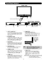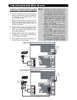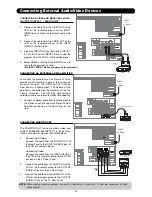
PUSH TO OPEN CONTROL DOOR
FRONT VIEW
PUSH EJECT
UPGRADE CARD
(SERVICE USE ONLY)
햲
햺
햹
햸
햴
햳
햶
햷
햲
FRONT POWER button
Press this button to turn the Plasma Television
ON/OFF. It can also be turned ON/OFF by remote
control. The “MAIN POWER” button must be at
stand-by mode.
햳
MENU/SELECT button
This button allows you to enter the MENU, making
it possible to set TV features to your preference
without using the remote. This button also serves
as the SELECT button when in MENU mode.
햴
HDMI-FRONT
Use the front HDMI input for extrenal devices such
as Set-Top-Boxes or DVD players equipped with an
HDMI output connection (see page 33 for reference).
햵
INPUT/EXIT button
Press this button to access the INPUT menu.
Press again to exit the MENU mode.
햶
CHANNEL selector
Press these buttons until the desired channel
appears in the top right corner of the TV screen.
These buttons also serve as the cursor down (
)
and up (
) buttons when in MENU mode.
햷
VOLUME level
Press these buttons to adjust the sound level. The
volume level will be displayed on the TV screen.
These buttons also serve as the cursor left (
) and
right (
) buttons when in MENU mode.
햸
POWER button
Television MAIN POWER button
This power button is for the complete system, and
must be turned ON/OFF manually. It is
recommended to leave the “MAIN POWER” to ON
condition (lights red) for stand-by mode.
NOTE:
When the “MAIN POWER” button is set to
OFF or the TV is unplugged, the clock will
stop and may eventually reset itself.
햽
Front Panel Controls
햵
FRONT PANEL CONTROLS
Upgrade Card
This card slot is for future software upgrades.
Hitachi will notify you if a software upgrade is
required for your TV. In order to receive written
notification, please complete and return your
warranty card.
햻
햹
The Main Power
button is located
on the broadside
bottom, under the
mark " ".
30
SERVICERS: Please check the Web Site frequently
for current software version.
http://www.hitachiserviceusa.com
Summary of Contents for P50H4011
Page 64: ...DW3U 63 FINAL WIRING DIAGRAM TABLE OF CONTENTS ...
Page 76: ...FINAL ASSEMBLY GUIDE TABLE OF CONTENTS 75 DW3U ...
Page 77: ...FINAL ASSEMBLY GUIDE 76 DW3U ...
Page 78: ...FINAL ASSEMBLY GUIDE 77 DW3U ...
Page 79: ...FINAL ASSEMBLY GUIDE 78 DW3U ...
Page 80: ...FINAL ASSEMBLY GUIDE 79 DW3U ...
Page 81: ...FINAL ASSEMBLY GUIDE 80 DW3U ...
Page 82: ...FINAL ASSEMBLY GUIDE 81 DW3U ...
Page 83: ...FINAL ASSEMBLY GUIDE 82 DW3U ...
Page 84: ...FINAL ASSEMBLY GUIDE 83 DW3U ...
Page 97: ...BACK TO TABLE OF CONTENTS 96 PRINTED CIRCUIT BOARDS DW3 U TERMINAL PWB Component side DW3 U ...
Page 98: ...PRINTED CIRCUIT BOARDS DW3 U TERMINAL PWB Solder side DW3 U 97 ...
Page 99: ...PRINTED CIRCUIT BOARDS DW3 U SD PWB Component side DW3 U 98 ...
Page 100: ...PRINTED CIRCUIT BOARDS DW3 U SD PWB Solder side DW3 U 99 ...
Page 102: ...PRINTED CIRCUIT BOARDS DW3 U FILTER PWB Component side DW3 U 101 Component side ...
Page 103: ...PRINTED CIRCUIT BOARDS DW3 U FILTER PWB Solder side DW3 U 102 Solder side ...
Page 123: ......

