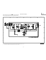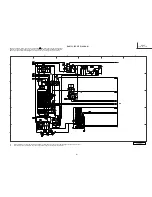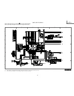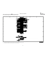
PRODUCT SAFETY NOTE: Components marked with a ! and shaded have special characteristics
important to safety. Before replacing any of these components, read carefully the PRODUCT SAFETY
•
All DC voltage to be measured with a tester (100 k
Ω
/V). Voltage taken on a complex color bar including a standard color bar signal.
•
Since this is a basic circuit diagram, the value of the parts is subject to be altered for improvement.
9
0
BASIC CIRCUIT DIAGRAM
NOTE of this Service Manual. Don't degrade the safety of the receiver through improper servicing.
1
2
3
4
5
6
A
B
C
D
E
SD
DW3U
SD 2 of 2
Summary of Contents for P50H4011
Page 64: ...DW3U 63 FINAL WIRING DIAGRAM TABLE OF CONTENTS ...
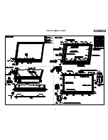
Page 76: ...FINAL ASSEMBLY GUIDE TABLE OF CONTENTS 75 DW3U ...
Page 77: ...FINAL ASSEMBLY GUIDE 76 DW3U ...
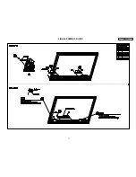
Page 78: ...FINAL ASSEMBLY GUIDE 77 DW3U ...
Page 79: ...FINAL ASSEMBLY GUIDE 78 DW3U ...
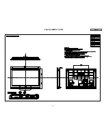
Page 80: ...FINAL ASSEMBLY GUIDE 79 DW3U ...
Page 81: ...FINAL ASSEMBLY GUIDE 80 DW3U ...
Page 82: ...FINAL ASSEMBLY GUIDE 81 DW3U ...
Page 83: ...FINAL ASSEMBLY GUIDE 82 DW3U ...
Page 84: ...FINAL ASSEMBLY GUIDE 83 DW3U ...
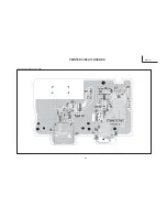
Page 97: ...BACK TO TABLE OF CONTENTS 96 PRINTED CIRCUIT BOARDS DW3 U TERMINAL PWB Component side DW3 U ...
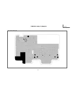
Page 98: ...PRINTED CIRCUIT BOARDS DW3 U TERMINAL PWB Solder side DW3 U 97 ...
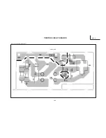
Page 99: ...PRINTED CIRCUIT BOARDS DW3 U SD PWB Component side DW3 U 98 ...
Page 100: ...PRINTED CIRCUIT BOARDS DW3 U SD PWB Solder side DW3 U 99 ...
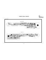
Page 102: ...PRINTED CIRCUIT BOARDS DW3 U FILTER PWB Component side DW3 U 101 Component side ...
Page 103: ...PRINTED CIRCUIT BOARDS DW3 U FILTER PWB Solder side DW3 U 102 Solder side ...
Page 123: ......

