


--- 30 ---
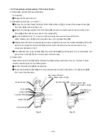
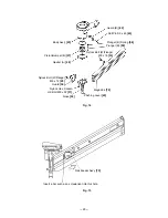
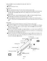
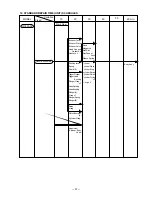
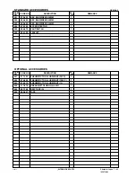
(a) Disassembly (See Fig. 16.)
Remove the Magazine [78] as described in section 10-2-(3).
Remove the Pushing Lever [45] as described in section 10-2-(3).
With the roll pin puller (3 mm (0.118") dia.), take out the Roll Pin D3 x 30 [52], and remove the Trigger [51],
Trigger Plunger [65], Plunger (B) Spring [58], Washer M5 [57] and Plunger (B) [59].
Insert the flat-blade screwdriver into the groove of the Trigger Valve Bushing [49], and loosen it by turning it
to the left, being careful not to damage the groove.
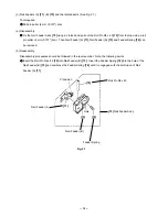
After removing the Trigger Valve Bushing [64], pull down strongly on the Valve Bushing [49] to remove the
Valve Bushing [49], Valve Sleeve (A) [54], Plunger (A) [48] and the Plunger Spring [46].
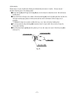
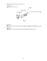
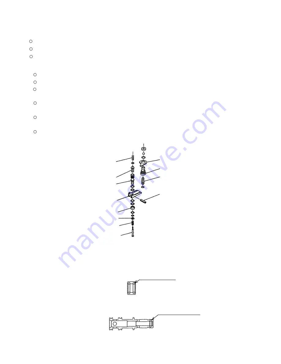
Remove the Plunger O-ring [56] inside the Valve Bushing [49] and the two O-rings (P-9) [53] inside Valve
Sleeve (A) [54] by means of a setting pin with a rounded tip (Fig. 17).
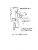
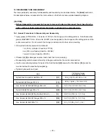
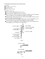
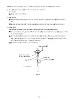
10-3. Disassembly and Reassembly of the Control Valve Section
Tools required:
Roll pin puller (3 mm (0.118") dia.)
Flat-blade screwdriver
Setting pin (with a rounded tip)
Fig. 16
Fig. 17
Trigger [51]
Plunger Spring [46]
Valve Bushing [49]
Plunger (A) [48]
Trigger Plunger [65]
Trigger Valve Bushing [64]
Valve Plate [63]
Roll Pin D3 x 30 [52]
Plunger (B) [59]
Valve Sleeve (A) [54]
O-ring (P-9) [53]
Plunger (B) Spring [58]
Valve Sleeve (A) [54]
Washer M5 [57]
Valve Bushing [49]
Plunger O-ring [56]
Summary of Contents for NR 83AA3
Page 45: ......