


--- 11 ---
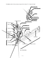
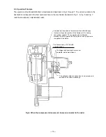
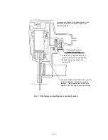
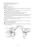
The <Bold> numbers in the figure below correspond to the numbers in "8-3. Operation Principle".
Fig. 3 Construction
Exhaust Vent < 3 >
Cylinder
Spring < 5 >
Return Air
Chamber < 8 >
Driver Blade < 7 >
Cylinder < 6 >
Piston < 4 >
Piston
Bumper < 9 >
Nose <10>
Pushing lever
Trigger
Control valve section
Safety valve portion
Trigger valve portion
Valve bushing
Plunger (B)
Nail stopper
Magazine
Magazine section
Switching device
(Valve sleeve (A))
Driving section
Output section
Firing gate
Nail feeder ass'y
Accumulator < 1 >
Control valve section
Grip rubber
Exhaust cover
Exhaust Valve < 2 >
Summary of Contents for NR 83AA3
Page 45: ......