background image

--- 14 ---

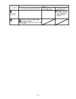
O-ring (I.D.10.7)
[58] (O-ring
mounted to the
outside of the
Valve Bushing
[57])

Part

NR 83A2

NR 83A

Inside diameter 10.7 mm

Caution

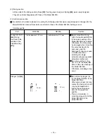
(2) Driving section

All the parts of the driving section (Nose [32], Pushing Lever Ass'y and Spring [46]) were newly designed.

They are not interchangeable with those of the Model NR 83A.

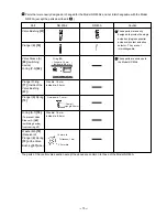
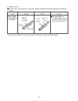
(3) Control valve section

Be careful not to make mistakes in mounting the following parts that were newly designed or changed for the

Model NR 83A2 because these parts are similar to those of the Model NR 83A but they are not

interchangeable.

Plunger (A) [56]

25 mm

26 mm

Inside diameter 11.5 mm

1

Never mount the O-ring
(S12) for the Model NR 83A
to the valve bushing of the
Model NR 83A2 by mistake.
Otherwise, the O-ring may
be damaged when mounting
the valve bushing to the
body ass'y, and the
damaged O-ring may cause
a malfunction when
selecting the single
actuation (single sequential
actuation) mechanism.
Do not mount the O-ring
(ID 10.7) for the Model NR
83A2 to the valve bushing of
the Model NR 83A.
Otherwise, air leakage may
occur.

Do not mount plunger (A)
for the Model NR 83A to the
Model NR 83A2.
Otherwise, plunger (A) may
contact the body ass'y and it
may be damaged when
raising the pushing lever
ass'y to the uppermost
position.
There is no problem in
mounting plunger (A) for the
Model NR 83A2 to the
Model NR 83A.

Summary of Contents for NR 83A2

Page 1: ...TECHNICAL DATA AND SERVICE MANUAL STRIP NAILER NR 83A2 SPECIFICATIONS AND PARTS ARE SUBJECT TO CHANGE FOR IMPROVEMENT LIST No E008 May 2003 N MODEL NR 83A2 Hitachi Power Tools ...

Page 2: ...ICE MANUAL a symbol s is are used in the place of company name s and model name s of our competitor s The symbol s utilized here is are as follows Symbols Utilized Competitors Company Name Model Name Dewalt D51845 R PASLODE F 350SRH Y SENCO 700XL P ...

Page 3: ...echanism 10 8 2 Interchangeability 12 8 3 Operation Principle 17 9 TROUBLESHOOTING GUIDE 21 9 1 Troubleshooting and Correction 21 9 2 Possible Causes and Corrections of Air Leakage 25 10 DISASSEMBLY AND REASSEMBLY 28 10 1 General Precautions in Disassembly and Reassembly 28 10 2 Disassembly and Reassembly of the Output Section 29 10 3 Disassembly and Reassembly of the Control Valve Section 33 10 4...

Page 4: ...ped with the same nailing depth adjustment mechanism as the Model NR 90AC2 the current Model NR 83A is not equipped 3 Changed construction so that the handle arm is fixed to the magazine with bolts and is easily detached by removing the bolts If the handle arm is damaged detach it from the magazine and replace only the handle arm with new one in the case of the current Model NR 83A it is impossibl...

Page 5: ...x 4 31 32 Hex bar wrench for M5 screw Code No 944458 1 Hex bar wrench for M6 screw Code No 944459 1 Hex bar wrench for M8 screw Code No 872422 1 Safety glasses Code No 875769 1 Full sequential actuation mechanism kit Code No 884069 Sequential trip mechanism kit Pneumatic tool lubricant 1 oz oil feeder Code No 877153 Pneumatic tool lubricant 4 oz oil feeder Code No 872042 Pneumatic tool lubricant 1...

Page 6: ...he push lever against the wood next pull the trigger to drive the nail First pull the trigger next press the push lever against the wood to drive the nail After nailing once nailing will not be possible again until the trigger is released and pressed again CONTACT ACTUATION MECHANISM First press the push lever against the wood next pull the trigger to drive the nail First pull the trigger next pre...

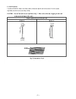
Page 7: ...es Applicable nail dimensions are shown below CAUTION Ensure that nails are as specified in Fig 1 Other nails will cause clogging of nails and subsequent damage to the nailer 7 mm 0 286 2 9 mm 0 113 50 mm 2 Minimum Plastic collated strip nails full head nails Fig 1 Dimensions of nail Maximum 7 6 mm 0 3 83 mm 3 1 4 21 deg ...

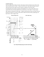
Page 8: ...il of 3 3 mm dia by 83 mm length 0 131 x 3 1 4 into nine sheets of 12 mm plywood 108 mm thick with the Model NR 83A2 a pressure of about 7 9 bar 8 kgf cm2 115 psi allows the nailer to drive the nail flush with the wood surface A pressure beyond this value causes the nail head to be driven below the wood surface Fig 2 should be used as reference data because those values vary depending on the type ...

Page 9: ...y pressing the push lever first against a workpiece and then pulling the trigger single shot operation and no nail is driven when pulling the trigger first and then pressing the push lever against a workpiece Please recommend the sequential trip mechanism kit to the customers who want to use it Salespersons must instruct the customers to read the Handling Instructions attached to the sequential tr...

Page 10: ...kgf cm 2 70 100 psi 529 mm x 325 mm x 127 mm 20 13 16 x 12 3 4 x 5 2 35 ltr cycle 0 074 ft 3 cycle 64 nails 2 strips Top loading 3 5 kg 7 7 lbs Tool less None 50 mm 90 mm 2 3 1 2 2 9 mm 3 8 mm 0 113 0 148 5 7 0 kgf cm 2 70 100 psi 324 mm x 334 mm x 107 mm 19 3 4 x 13 1 8 x 4 1 4 2 05 ltr cycle 0 109 ft 3 cycle 64 nails 2 strips Bottom loading 3 9 kg 8 6 lbs With wrench None 50 mm 90 mm 2 3 1 2 2 9...

Page 11: ...ustomers who want to use it Refer to the leaflet attached together with the Instruction Manual for details 7 1 Instruction Manual Although every effort is made in each step of design manufacture and inspection to provide protection against safety hazards the dangers inherent in the use of any pneumatic tool cannot be completely eliminated Accordingly general precautions and suggestions for use of ...

Page 12: ...listed in the Instruction Manual provided with each unit While there are no specific safety regulations there are related items in various general safety regulations with which the salespersons should be familiar in order to properly advise the customer Please check your national and or local regulations for applicable items Some applicable items are outlined below The U S A OSHA 1926 102 Eye and ...

Page 13: ...socket hd bolt M8 x 25 to the nylock hex socket hd bolt M8 x 22 The screw hole is therefore different in depth and the bolt for the Model NR 83A cannot be used for the Model NR 83A2 The grip tape wound around the handle was changed to the ring type grip rubber The grip rubber is common to the Model NR 83AA2 Conventional grip tape is supplied as a repair part because the grip rubber cannot be mount...

Page 14: ...r 8 Driver Blade 7 Cylinder 6 Piston 4 Piston Bumper 9 Nose 10 Pushing lever ass y Trigger Control valve section Safety valve portion Trigger valve portion Valve bushing Plunger B Nail feeder Magazine Magazine section Switching device Valve sleeve A Driving section Output section Exhaust Valve 2 Exhaust cover Ribbon spring ass y Grip rubber Control valve section ...

Page 15: ...ot chamfered Caution 1 mm dia hole Color Milky white Nose 32 M8 x 25 Never mount the exhaust valve for the Model NR 83A to the Model NR 83A2 by mistake Otherwise it may cause a malfunction when selecting the single actuation single sequential actuation mechanism Note that the driving force may be decreased a little though no malfunction may occur if the exhaust valve for the Model NR 83A2 is mount...

Page 16: ... Cover 2 Part NR 83A2 NR 83A Top Cover 2 M6 x 25 Caution Hex Socket Hd Bolt W Flange M6 x 45 1 M6 x 45 Spring washer Exhaust Cover 4 Hex Socket Hd Bolt W Sp Washer M6 x 25 3 Spring washer Hex Socket Hd Bolt W Sp Washer M6 x 25 3 For mounting the Exhaust Cover 4 3 Parts that are interchangeable as assemblies The hex socket hd bolt M6 x 45 and the spring washer for the Model NR 83A are interchangeab...

Page 17: ... 56 25 mm 26 mm Inside diameter 11 5 mm 1 Never mount the O ring S12 for the Model NR 83A to the valve bushing of the Model NR 83A2 by mistake Otherwise the O ring may be damaged when mounting the valve bushing to the body ass y and the damaged O ring may cause a malfunction when selecting the single actuation single sequential actuation mechanism Do not mount the O ring ID 10 7 for the Model NR 8...

Page 18: ...ng device from coming off Washer M5 72 Receiver of Plunger B Spring 73 at the Valve Bushing 57 side Thickness 1 mm 10 mm dia 5 3 mm dia Wire dia 1 5 mm Inside dia 6 5 mm Outside dia 7 4 mm Overall length 28 mm Wire dia 1 5 mm Inside dia 4 5 mm O ring P9 Wire dia 1 9 mm Inside dia 8 8 mm Plunger B 74 These parts are exclusive to the Model NR 83A2 Parts that were newly designed or changed for the Mo...

Page 19: ... to the body ass y is different Nylock Bolt W Flange M8 x 16 35 Handle Arm B 37 Magazine 82 Washer Nylon nut Spring washer M5 x 25 4 Magazine section Parts that were newly designed or changed for the Model NR 83A2 and not interchangeable with the Model NR 83A 1 The parts of the magazine section except the above are common to those of the Model NR 83A ...

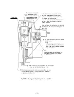
Page 20: ...e compressed air source air hose is connected to the nailer Air pressure is applied to the lower surface of the flanges located at the center portion of the Cylinder 6 forcing the cylinder upward The compressed air is thereby blocked from the upper end of the cylinder and no pressure is applied to the piston The Accumulator 1 fills with compressed air The trigger and pushing lever are not operated...

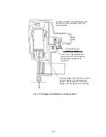
Page 21: ...lever are operated simultaneously NOTE If either the trigger or pushing lever are operated individually compressed air will not enter the valve air passage and the nailer will not function When the trigger and pushing lever are operated simultaneously the exhaust vents are closed Compressed air is applied to the upper side of the Exhaust Valve 2 forcing it downward and closing the Exhaust Vent 3 A...

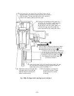
Page 22: ...he position illustrated The lower surface of the Piston 4 contacts the Piston Bumper 9 and prevents air leakage If the upper surface of the Piston Bumper 9 is damaged some air will leak As there is no o ring installed here a very small amount of air will leak from the slight clearance between the components If the operator s grip is loosened air will leak ...

Page 23: ... remaining air pressure at the lower end of the piston is discharged through the clearance between the Piston Bumper 9 and the Driver Blade 7 When the air pressure at the upper side of the piston lowers the air pressure within the Return Air Chamber 8 pushes the piston upward NOTE If the clearance were larger the piston would not return if it were smaller driving force would be decreased When the ...

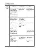
Page 24: ...ot be driven Check if the magazine is normally loaded with specified nails Check the nail feeding section for abnormal conditions burrs fatigued deformed damaged Check if the nail feeder operates smoothly in the magazine Check if the nails one strip move smoothly in the magazine Check if nails one strip are fed smoothly into the nail injection port of the nose Use specified nails Remove the abnorm...

Page 25: ...f cm2 Replace the piston ring Piston O ring is worn or damaged Piston bumper is abnormal dislocated deformed or damaged Cylinder ring is abnormal dislocated deformed or damaged Driver blade is abnormal deformed burrs damaged or fatigued Cylinder s internal surface is abnormal deposits of dirt or worn Control valve section Plunger A valve piston B valve bushing A or valve bushing B is abnormal gall...

Page 26: ...de is worn Workpiece is very hard Problem Possible cause Inspection method Remedy 2 Nails are bent when being driven Check if the adjuster is raised too high See item 1 Check if the driver blade tip is abnormally worn Drive a nail into soft wood workpiece and check if the nail is bent Turn the adjuster to the lower position to decrease the pressure See item 1 Replace the driver blade Do not use un...

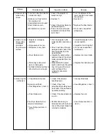
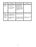
Page 27: ... or broken Problem Possible cause Inspection method Remedy 5 Single actuation impossible Set the single actuation contact actuation selector to the single actuation Perform idle driving once and keep the nail feeder pulled backward Check that no air leaks from the inside of plunger B and valve sleeve A Replace the defective part 6 Piston actuates just by pulling the trigger when single actuation i...

Page 28: ... 25 9 2 Possible Causes and Corrections of Air Leakage Air leakage repair location A B C G D E F ...

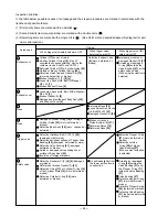
Page 29: ...k part Cause When trigger valve safety valve are OFF When trigger valve safety valve are ON Inspection priorities In the table below possible causes of air leakage and their repair procedures are marked in accordance with the likelihood of possible failure 1 First priority items are marked with an asterisk 2 Second priority items seal portions are marked with a double circle 3 Remaining items are ...

Page 30: ...he Body Ass y 25 or Cap 40 Cap Air leak part Cause When trigger valve safety valve are OFF When trigger valve safety valve are ON When trigger valve ON safety valve OFF G Scratched or damaged O ring 60 inside Valve Sleeve A 69 When single actuation is selected Safety valve continued F ...

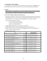
Page 31: ...0 cc oil feeder Code No 877153 4 oz 120 cc oil feeder Code No 874042 1 quart 1 ltr can Code No 876212 If Gasket B 5 is damaged replace it and check that no air is leaking Be especially careful to prevent the entry of foreign particles into the control valve section Use the conventional grip tape for repair of the Grip Rubber 38 because the Grip Rubber 38 cannot be mounted without the specifically ...

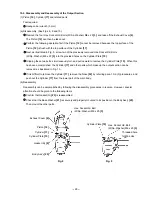
Page 32: ...to remove the Cylinder Plate 15 When this has been accomplished the Cylinder 17 and other parts which make up the output section can be removed as illustrated in Fig 10 If it is difficult to remove the Cylinder 17 remove the Nose 32 by referring para 10 2 3 procedures and push out the Cylinder 17 from the lower part of the main body b Reassembly Reassembly can be accomplished by following the disa...

Page 33: ...and Gasket F 6 b Reassembly Reassembly can be accomplished by following the disassembly procedures in reverse However special attention should be given to the following items Be sure to check that the Exhaust Valve 9 is orange and provided with a 1 mm dia hole Fig 12 before reassembly Note that mounting a wrong exhaust valve may cause a malfunction Gasket C 8 and Gasket F 6 should be replaced with...

Page 34: ...Then Piston Bumper B 27 and Gasket A 28 can be removed together with the Nose 32 and pushing lever ass y Fig 14 b Reassembly Disassembly procedures should be followed in the reverse order Note the following points Plunger B Spring 73 Plunger B 74 and Washer M5 72 are apt to be removed during disassembly Be sure to check that Plunger B Spring 73 Plunger B 74 and Washer M5 72 are mounted without fai...

Page 35: ...W Flange M8 x 16 35 Plunger B 74 Roll Pin D3 x 45 45 Body Ass y 25 Fig 14 Pushing lever ass y Pushing Lever B 47 Washer 52 Pushing Lever A 51 Steel Ball D3 175 50 Adjuster Spring 49 Adjuster 48 Hex Socket Hd Bolt M6 x 12 53 Plunger B Spring 73 Guard B 44 Guard A 31 Nylock Hex Socket Hd Bolt M8 x 22 33 Pushing lever ass y Ribbon Spring 76 Nail Feeder 75 ...

Page 36: ...rewdriver Setting pin with a rounded tip Trigger 59 Plunger Spring 54 Valve Bushing 57 Plunger A 56 Trigger Plunger 66 Trigger Valve Bushing 65 Valve Plate 64 Roll Pin D3 x 30 68 Plunger B 74 b Reassembly Reassembly can be accomplished by following the disassembly procedures in reverse However special attention should be given to the following items Plunger Spring 54 and Plunger B Spring 73 are sm...

Page 37: ...he following items The two Adjuster Springs 49 and the Steel Ball D3 175 50 are very small and apt to be lost Be careful when handling them After reassembly check that the Adjuster 48 turns smoothly by hand 10 4 Disassembly and Reassembly of the Driving Section Tools required Hexagonal bar wrench 5 mm and 6 mm Roll pin puller 3 mm 0 118 dia Fig 18 Pushing Lever A 51 Washer 52 Nose 32 Nylock Hex So...

Page 38: ...ine section according to 10 2 3 Remove the loose High Tension Bolt M6 x 18 29 to remove the Nail Feeder 75 and the Ribbon Spring 76 Remove the two Hex Socket Hd Bolts M6 x 12 53 to remove Handle Arm B 37 Remove the Hex Socket Hd Bolts M5 x 45 84 and the Hex Socket Hd Bolts M4 x 15 85 to remove Stop Lever 87 Sleeve 83 and the related parts 10 5 Disassembly and Reassembly of the Cap and the Magazine...

Page 39: ...ly Reassembly can be accomplished by following the disassembly procedures in reverse Note the following points Press the Magazine 82 against the Nose 32 side to minimize the clearance between the Magazine 82 and the Nose 32 as described in 10 2 3 Mount the Stop Lever 87 and the related parts as shown in Fig 21 When mounting the Stopper Spring 89 hook an end of the Stopper Spring 89 on the Stop Lev...

Page 40: ...y pulling the Trigger 59 Check that the Model NR 83A2 does not operate just by pressing the pushing lever ass y against a test piece wood etc Check that the Model NR 83A2 operates by pulling the Trigger 59 first then pressing the pushing lever ass y against a test piece At this time pull the Nail Feeder 75 backward and hook it on the Stop Lever 87 see Fig 21 4 Set Valve Sleeve A 69 to single actua...

Page 41: ... Valve 12 STANDARD REPAIR TIME UNIT SCHEDULES MODEL 10 20 30 40 Fixed Variable NR 83A2 Work Flow Exhaust Cover Exhaust Piece Exhaust Valve Head Cap and Gasket Set Gasket x 4 60 min 50 Tail Cover Magazine Nail Feeder Ribbon Spring Pushing Lever A Pushing Lever B Adjuster Spring Guard B General Assembly Cylinder Cylinder Plate Cylinder Ring Cylinder Spring Cylinder Guide Cylinder O ring x 3 O ring x...

Page 42: ...5 6 7 8 9 10 11 12 13 14 20 21 13 22 13 23 24 25 26 27 28 29 30 31 32 33 35 36 37 39 41 42 501 502 503 504 505 506 43 44 45 46 47 48 49 50 52 53 54 55 56 57 58 59 60 61 62 63 64 65 66 67 68 69 70 71 72 73 74 75 76 77 78 79 80 81 82 83 84 85 87 88 89 53 86 30 29 51 40 34 38 15 16 17 18 19 ...

Page 43: ...877 322 BASE WASHER 1 22 877 310 CYLINDER GUIDE 1 23 877 327 GASKET G 1 24 884 069 WARNING LABEL 1 25 883 506 BODY ASS Y 1 INCLUD 38 26 877 315 CYLINDER O RING I D 63 9 1 27 883 511 PISTON BUMPER B 1 28 877 334 GASKET A 1 29 878 426 HIGH TENSION BOLT M6X18 2 30 949 455 SPRING WASHER M6 10 PCS 2 31 884 061 GUARD A 1 32 884 060 NOSE 1 33 883 492 NYLOCK HEX SOCKET HD BOLT M8X22 4 34 949 518 ROLL PIN ...

Page 44: ... 121 TRIGGER PLUNGER 1 67 874 820 PLUNGER O RING 1 68 949 866 ROLL PIN D3X30 10 PCS 1 69 884 116 VALVE SLEEVE A 1 70 876 316 O RING S 7 1 71 878 723 PLUNGER O RING 1 72 949 424 WASHER M5 10 PCS 1 73 884 115 PLUNGER B SPRING 1 74 884 114 PLUNGER B 1 75 877 393Z NAIL FEEDER 1 76 878 422 RIBBON SPRING 1 77 878 418 NEEDLE ROLLER 1 78 876 465 NYLON NUT M4 1 79 949 453 SPRING WASHER M4 10 PCS 1 80 877 3...

Page 45: ... 501 872 422 HEX BAR WRENCH 6MM 1 502 944 459 HEX BAR WRENCH 5MM 1 503 944 458 HEX BAR WRENCH 4MM 1 504 875 769 EYE PROTECTOR 1 505 882 413 CAUTION TAG 1 506 882 414 LEAFLET 1 601 881 768 GRIP TAPE A 1 602 880 407 TAPE 1 603 877 153 PNEUMATIC TOOL LUBRICANT 30CC 1 604 874 042 PNEUMATIC TOOL LUBRICANT 120CC 1 605 876 212 PNEUMATIC TOOL LUBRICANT 1L 1 606 317 918 GREASE ATTOLUB NO 2 500G 1 ...

Page 46: ......
Reviews: