


−
7
−
(4) Installation of the assembly reassembled in step (3) into the Housing (A) and (B) [33].
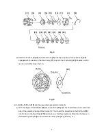
(a) Install the Pushing Button [37] into the Housing (B) [33]. (See Fig.13.)
(b) Install the assembly reassembled in step (3) into the Housing (A) [33]. Note that the projections on
the Front Case [11] and the Motor Spacer [26] are engaged in the recess in the Housing (A) [33].
(See Fig.14.)
(c) Set the assembly reassembled in step (b) to the Housing (B) [33] and secure it with the seven
Tapping Screws (W/Flange) D3 x 16 [28].
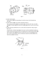
(d) Verify proper operation of the Cap [6].
When the assembly procedure up to step (c) is completed, make sure that the number “1” on the Cap
[6] and the drill mark “
” are in alignement with the triangle mark on the Housings (A) and
(B) [33]. If the number “1” on the Cap [6] or drill mark “
” cannot reach the triangle mark on the
Housing (A) and (B) [33], correctly re-install the Cap [6] referring to step (2) (b) as it is improperly
installed.
Fig. 13 Fig. 14
[33]
[33]
[37]
Projection
Recess


