


−
3
−
1-1-2. Reassembly
Reassembly can generally be carried out as the reverse of the disassembly procedure, with some items to
be noted as follows.
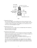
(1) Reassembly of the power supply unit
(a) Be sure to perform wiring connections as indicated in the wiring diagram (Fig.5).
Fig. 5
(Note) Do not deform the bendable legs of the FET attached to the DC-Speed Control Switch [36].
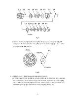
(b) Pay attention to the polarity of the Motor [27] when soldering the Internal Wires [35] and [38] to the
Motor [27]. The red marking side of the Motor [27] is positive. (See Fig.6.)
(Note) When installing the Motor Spacer [26] to the Motor [27], align the negative terminal of the
Motor [27] with the marking on the Motor Spacer [26] and tighten with the Machine Screw
M4 x 6 [30] and the Spring Washer M4 [31].
(c) Apply grease (Hitachi Motor Grease No.29) to the pinion pressed into the Motor [27].
Fig. 6
Negative side
Marking
[26]
[27]
Red marking
Positive side
Motor Spacer [26]
Motor [27]
Internal Wire(Red) [35]
DC-Speed Control Switch [36]
Internal
Wire(Black) [38]
Machine Screw
M4 x 6 [30]
Spring Washer M4 [31]
Machine Screw M3 x 5 [34]
Flag-shaped terminal
Terminal
Housing(B) side
Terminal
Housing(A) side
Fin [43]
Bind Screw M3 x 7 [42] [42]
Terminal Support(A) [41]


