background image

-25-

Fig. 24

Cord ass’y

Gray

Noise
suppressor

Speed control SW

Reversing SW

Choke coil

White or blue

Black or brown

Brown

Blue

Black

St

St

White

Choke coil

Red

Fig. 25

9. Wiring diagrams

(1) Product with noise suppressor

(2) Product without noise suppressor

Cord ass’y

Black

Speed control SW

Reversing SW

Red

Black or brown

St

White

Gray

Brown

Blue

White or blue

Summary of Contents for DH 22PH

Page 1: ...e as follows 1 Although the Model DH 22PH is a 3 mode type rotary hammer it is more compact and lightweight than the 2 mode type competitors in the same class 318 mm in overall length and 2 1 kg in weight 2 The internal pressure adjustment mechanism prevents grease from leaking LIST No F407 Jun 2009 1 Rotation and hammering function x Drilling anchor holes x Drilling holes into concrete tile brick...

Page 2: ...ki com manual_view_export Throughout this TECHNICAL DATA AND SERVICE MANUAL a symbol s is are used in the place of company name s and model name s of our competitor s The symbol s utilized here is are as follows Competitors Symbols utilized Company name Model name B BOSCH GBH2 23RE C MAKITA HR2230 ...

Page 3: ...d 9 3 Comparison of Chiseling Performance 9 PRECAUTIONS ON SALES PROMOTION 10 1 Safety Instructions 10 REFERENCE MATERIALS 11 1 Lubrication 11 2 Tool Structure 11 3 3 Mode Changeover Mechanism 14 4 Drill Bits 16 5 Tool Retainer Section 17 6 Dust Collector B 17 REPAIR GUIDE 19 1 Precautions on Disassembly and Reassembly 19 STANDARD REPAIR TIME UNIT SCHEDULES 30 Assembly Diagram for DH 22PH ...

Page 4: ...ass HITACHI Maker Model DH 22PH B C Overall length 318 mm 342 mm 357 mm Weight 2 1 kg 2 3 kg 2 5 kg Hitachi s own internal pressure adjustment mechanism An air passage is provided as shown below to let out air inside the gear cover and let outside air in the gear cover This passage is sandwiched between felt packings to allow only air to pass As a result fluctuations in internal pressure are minim...

Page 5: ...rse min 1 0 to 910 Full Load bpm min 1 0 to 5 600 Mode 3 Variable speed YES Reverse switch type Push button Handle No Soft grip Gear cover No mm 318 Overall length Inch 12 to 1 2 No load vibration level Tri axial measured m s2 12 1 Full load vibration level Tri axial measured m s2 13 2 No load noise level measured dB 95 2 Full load noise level measured dB 89 4 kg 2 1 Weight lbs 4 6 SPECIFICATIONS ...

Page 6: ...3594 5 0 160 100 303578 14 0 303595 5 5 303576 14 3 166 100 303596 6 0 110 50 303577 14 3 260 200 303609 6 0 303579 14 5 166 100 303597 6 4 303580 14 5 260 200 303610 6 5 303581 15 0 303598 7 0 303582 16 0 166 100 303599 7 5 303583 16 0 260 200 303611 8 0 303584 16 5 303600 8 5 303585 17 0 166 100 303601 9 0 303586 17 0 260 200 308485 9 5 303587 17 5 166 100 303602 10 0 160 100 303588 17 5 260 200...

Page 7: ...lender shaft 2 Adapter for slender shaft Outer dia mm Overall length mm Effective length mm Code No Code No 3 4 306369 3 5 90 45 306368 306370 Drill bit taper shank 1 Drill bit taper shank 2 Taper shank adapter 3 Cotter Outer dia mm Code No Type Code No Code No 1100 12 3 12 7 14 3 14 5 17 5 944460 944461 993038 944462 944500 944463 Morse taper No 1 303617 944477 13 mm hammer drill chuck Part name ...

Page 8: ...ing adapter B 160 303622 W 3 8Anchor setting adapter A 260 302974 W 3 8Anchor setting adapter B 260 302977 Internal cone type External cone type 3 Bolt placing operations with chemical anchor rotation hammering Standard sockets available on the market 12 7 mm 1 2 Chemical anchor adapter SDS plus shank 19 mm 3 4 Chemical anchor adapter SDS plus shank Part name Code No 12 7 mm 1 2 Chemical anchor ad...

Page 9: ...n mounting the drill chuck onto chuck adapter G Stamped bit No Tip thickness 5 Drilling holes and driving screws rotation only Part name Code No Chuck adapter G 303623 13 mm drill chuck with chuck wrench 321814 Special screw M6 left hand threaded 981122 1 Cross recessed head Phillips bit 2 Slotted head minus bit Overall length 65 mm Overall length 70 mm For use with cross recessed head Phillips sc...

Page 10: ... hammer and hammer drill 7 Dust cup and dust collector B x Containing 500 g x Containing 30 g x Containing 70 g Code No 980927 Code No 981840 Code No 308471 Code No 971787 Code No 306885 x Dust cup x Dust collector B ...

Page 11: ... 1 0 to 5 600 0 to 4 400 0 to 4 050 Mode 3 2 2 Variable speed Yes Yes Yes Reverse switch type Push button CB holder CB holder Handle No Yes Yes Soft grip Gear cover No No Yes mm 318 342 357 Overall length Inch 12 to 1 2 13 to 7 16 14 to 1 16 No load vibration level Tri axial measured m s2 12 1 12 4 8 7 Full l load vibration level Tri axial measured m s2 13 2 16 8 16 2 No l load noise level measure...

Page 12: ...tions x Direction Downward drilling x Pushing force 98 N 10 kgf x Test material Concrete panel with compression strength of 2 352 N cm2 240 kgf cm2 3 Comparison of Chiseling Performance Chiseling performance varies considerably depending on the work conditions Use the factory test results shown in Fig 2 for comparison purposes only DH 24PC3 DH 22PH 0 10 20 30 40 Chiseling amount kg 30 min Voltage ...

Page 13: ... any electric tool cannot be completely eliminated Accordingly the Handling Instructions list general precautions and suggestions on the use of electric power tools and specific precautions and suggestions on the use of the Rotary Hammer to enhance the safe efficient use of the tool by the customer Salespersons must be thoroughly familiar with the contents of the Handling Instructions in order to ...

Page 14: ...y means of a slip mechanism and both rotate together The end of the cylinder also functions as the drill bit retainer The cylinder is key connected to the inserted drill bit by means of two key rails and a steel ball and transmits rotation to the drill bit Piston reciprocating mechanism The Model DH 22PH adopts a spiral drive system i e mechanism using a reciprocating bearing resulting in a more c...

Page 15: ...striking prevention mechanism The idle hammering prevention mechanism in the Model DH 22PH differs from that of conventional rotary hammers When the drill bit is lifted from the concrete surface after drilling the second hammer moves to the position indicated by the continuous line in Fig 4 and the protrusion at the tip of the striker is gripped by O ring C mounted between the hammer holder and da...

Page 16: ...does not transmit rotation Even if the drill bit comes into contact with a reinforcing bar within the concrete causing sudden excessive torque the slip mechanism functions to prevent damage to the gears and possible loss of tool control by the operator slip torque setting applied to the tool shaft 1 0 to 2 0 kgm Sealed and dust proof construction The gear cover is totally enclosed by oil seals O r...

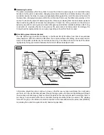
Page 17: ...e clutch via the spline of the second shaft Claws on the end surface of the clutch engage with matching claws of the reciprocating bearing at A in the figure to convert the rotation into reciprocating motion The three claws on the tip of the second shaft are constantly engaged with the three matching claws of the pinion sleeve and second shaft rotation is transmitted to the pinion sleeve Then the ...

Page 18: ... rotation is transmitted to the reciprocating bearing and hammering stops Conversely for the rotation only function the pinion sleeve engages with the second pinion at B in the figure to transmit rotation to the pinion sleeve 3 Hammering only Fig 8 Set the change lever to hammering only mark The pin of the change lever moves the second pinion to the motor side Engagement is released between the pi...

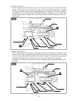
Page 19: ...ill bit by two key rails provided in the tool holding section A steel ball is used to prevent the bit from falling out A drill bit with a diameter of 8 mm has a service life of about 300 holes when drilling holes into concrete to a depth of 30 mm If reground before the end of its service life the drill bit will continue to provide efficient drilling Figure 10 shows the regrinding angle ...

Page 20: ...llector B permits drilling down to a depth of about 72 mm When using dust collector B be sure to securely fasten it to the grip on the main body with socket adapter B Although socket adapter B rotates together with the tool shank there is a steel ball between the outer race and socket that serves as a ball bearing Should the dust cover be forced against the concrete surface it will not rotate even...

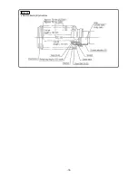
Page 21: ... 18 Fig 12 x Dust collector B structure ...

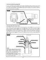
Page 22: ... 2 Now you can remove the Grip 3 Ball Holder 4 Steel Ball D7 0 23 Holder Plate 5 Holder Spring 6 and Washer B 7 from the Cylinder 25 2 Disassembly of the hammering mechanism Set the Change Lever 17 to rotation and hammering marks remove the Tapping Screws W Flange D4 x 30 black 9 from the Gear Cover A 10 and then remove the Gear Cover A 10 Leave the lock plate assembly mounted in the removed Gear ...

Page 23: ...ht position and then use the Gear Cover J J 352 No 331451 and hand press to remove the Cylinder 25 from the Gear Cover A 10 The Sleeve 13 can then be removed from the Cylinder 25 After removing the Cylinder 25 from the Gear Cover A 10 be careful not to lose the Steel Balls D5 556 24 3 pieces Retaining Ring D15 21 Change Lever 17 Tilt the ring at 10q to 20q with the main shaft Main shaft Fig 16 Gea...

Page 24: ... D5 556 24 3 pieces from the cylinder insert the Spring Hook J 201 No 970977 into the Cylinder 25 from the hole in the cylinder and then disengage the O Ring A 32 from inside the cylinder with a spring hook You can remove the second hammer assembly from the Cylinder 25 by pushing out the second hammer assembly from the bit side of the cylinder Fig 18 ...

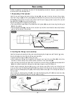
Page 25: ...o the bit side of the cylinder 2 Inserting the Change Lever assembly Insert the change lever assembly into the gear cover while aligning the change lever with rotation mark Note the following when inserting the change lever assembly x Always insert the Spring C 22 into the gear cover x When inserting the change lever assembly into the gear cover push the Lock Plate 39 in the arrow direction so tha...

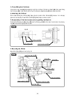
Page 26: ...apply grease to its periphery Press fit the Oil Seal 12 while being careful not to tilt it 5 Reassembly of the internal pressure regulating mechanism Push the Felt Packing A 49 Valve 50 and Felt Packing B 51 in this order into the Inner Cover Ass y A 52 so that all are tightly fitted in place 6 Mounting the Piston Mount the Piston 35 as shown in Fig 22 Felt Packing B 51 Valve 50 Felt Packing A 49 ...

Page 27: ...mbled unit while paying attention to the positions of the Piston 35 shaft Cylinder 25 shaft Second Shaft 44 and Second Pinion 40 shaft When the Second Shaft 44 touches the pinion sleeve assembly turn the Grip 3 to engage the Second Shaft 44 Second Pinion 40 Second Gear 26 and pinion sleeve assembly with one another and then place the end faces of the Gear Cover A 10 assembly and Housing Handle Cov...

Page 28: ...oke coil White or blue Black or brown Brown Blue Black St St White Choke coil Red Fig 25 9 Wiring diagrams 1 Product with noise suppressor 2 Product without noise suppressor Cord ass y Black Speed control SW Reversing SW Red Black or brown St White Gray Brown Blue White or blue ...

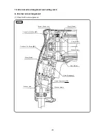
Page 29: ...n Choke coil Black Stator Gray Stator Red Stator Blue Choke coil Black or brown White Stator White Stator White or blue t Noise Suppressor 73 Fig 26 10 Internal wire arrangement and wiring work A Internal wire arrangement 1 Product with noise suppressor ...

Page 30: ... 27 Black Stator Gray Stator White Stator Red Stator Blue CB Black or brown White or blue White Stator Brown CB Fig 27 2 Product without noise suppressor ...
Page 31: ...ach lead wire to confirm that the lead wires do not come off To disconnect the lead wires insert a small flat blade screwdriver into the openings near the terminals and pull out the lead wires 2 Wiring of the speed control switch Insert each cord into terminals 1 and 2 of the speed control switch as shown in Fig 29 and then tighten the screw tightening torque 0 6 0 2 Nxm 6 2 kgfxcm 5 2 1 7 in lbs ...

Page 32: ...ing a 500 VDC megohm tester Dielectric strength 4 000 VAC minute with no abnormalities for 220 V 240 V 110 V for U K products 2 500 VAC minute with no abnormalities for 110 V 120 V Except for U K products 12 No load current values After no load operation for 30 minutes the no load current values should be as follows Voltage V 110 120 220 230 240 Current A max 3 0 2 8 1 6 1 5 1 4 ...

Page 33: ... Plate Second Pinion DH22PH Cord Armor Switch Cord Gear Cover A Oil Seal Ball Bearing 6904DDPS2L Cylinder Second Gear Spring A Housing Handle Cover Set Stator Armature Ass y O ring S 24 Ball Bearing 609DDC3PS2 L Ball Bearing 608VVC2PS2L Front Cap Grip Ball Holder Holder Spring Steel Ball D7 0 Change Lever O ring S 15 Striker O ring A Piston O ring A Piston Pin Washer C Second Hammer O ring B Gener...

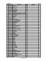
Page 34: ... 11 12 13 14 16 18 19 20 21 23 24 25 27 28 29 30 31 32 33 34 35 36 52 37 38 39 40 41 43 44 45 46 47 48 53 54 55 56 57 58 59 60 61 62 63 65 66 68 71 69 70 69 73 75 76 77 80 79 22 49 50 51 72 67 501 502 503 74 78 15 64 Model DH 22PH ROTARY HAMMER LIST NO F407 E1 2009㨯6㨯19 ...

Page 35: ...ING RING D15 1 22 331 302 SPRING C 1 23 959 156 STEEL BALL D7 0 10 PCS 1 24 959 154 STEEL BALL D5 556 10 PCS 3 25 331 307 CYLINDER 1 26 331 309 SECOND GEAR 1 27 331 310 SPRING A 1 28 331 311 WASHER A 1 29 320 846 RETAINING RING D28 1 30 331 312 SECOND HAMMER 1 31 301 672 O RING B 1 32 331 308 O RING A 1 33 331 296 STRIKER 1 34 301 670 O RING A 1 35 331 300 PISTON 1 36 327 870 O RING A 1 37 322 798...

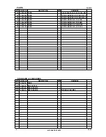
Page 36: ...X HKG 68 324 538 INTERNAL WIRE A BLUE 1 FOR VEN THA IND SYR INA SIN KUW USA CAN MEX HKG 69 955 203 BRUSH HOLDER 2 70 324 537 INTERNAL WIRE A BROWN 1 FOR VEN THA IND SYR INA SIN KUW USA CAN MEX HKG 71 999 041 CARBON BRUSH 1 PAIR 2 72 331 454 SWITCH 1P PILLAR TYPE 1 73 930 039 NOISE SUPPRESSOR 1 EXCEPT FOR VEN THA IND SYR INA SIN KUW USA CAN MEX HKG 74 981 373 TUBE D 2 FOR CORD 75 953 327 CORD ARMOR...

Page 37: ...56Z CORD 1 CORD ARMOR D8 8 FOR CHN 80 500 440Z CORD 1 CORD ARMOR D8 8 FOR HKG 80 323 974 CORD 1 CORD ARMOR D10 1 FOR TPE 80 500 475Z CORD 1 CORD ARMOR D8 8 FOR KOR DESCRIPTION REMARKS 501 331 439 CASE 1 502 324 548 SIDE HANDLE 1 503 303 709 DEPTH GAUGE 1 503 310 331 DEPTH GAUGE 1 FOR USA CAN MEX 4 06 09 ALTERNATIVE PARTS NO USED CODE NO ITEM NO STANDARD ACCESSORIES NO USED CODE NO ITEM NO ...

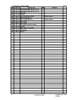
Page 38: ...DS W3 8 X 160L 1 624 302 974 ANCHOR SETTING ADAPTER A SDS W3 8 X 260L 1 625 302 979 ANCHOR SETTING ADAPTER B SDS W1 4 X 260L 1 626 302 978 ANCHOR SETTING ADAPTER B SDS W5 16 X 260L 1 627 303 622 ANCHOR SETTING ADAPTER B SDS W3 8 X 160L 1 628 302 977 ANCHOR SETTING ADAPTER B SDS W3 8 X 260L 1 629 303 334 CHUCK HANDLE 1 630 930 515 CHUCK WRENCH 10G 1 631 303 332 HAMMER DRILL CHUCK SET 13MM 1 INCLUD ...

Page 39: ... ASS Y 1 INCLUD 656 657 656 306 910 SOCKET ADAPTER B 1 657 986 802 DUST COLLECTOR ASS Y 1 INCLUD 658 664 658 986 803 DUST COVER 1 659 986 804 SEAL COVER 1 660 948 310 RETAINING RING FOR D30 SHAFT 1 661 958 063 WASHER 1 662 959 150 STEEL BALL D6 35 10 PCS 19 663 986 805 OUTER RACE 1 664 986 806 SOCKET 1 6 Printed in Japan 06 09 090619N ALTERNATIVE PARTS NO USED CODE NO ITEM NO OPTIONAL ACCESSORIES ...

Reviews: