-22-
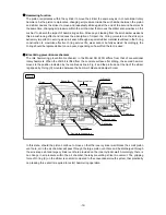
Cylinder
[25]
Second hammer assembly
Steel Ball D5.556
[24]
O-Ring (A)
[32]
Bit side
Fig. 19
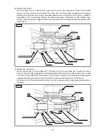
Central Hole of Lock Plate
[39]
Change lever pin
Lock Plate
[39]
Perform reassembly by reversing the order of the disassembly procedure. However, special attention
should be given to the following items.
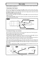
1. Reassembly of the Cylinder
Insert the second hammer assembly into the Cylinder
[25]
, and push it into the bit side of the cylinder.
Insert the O-Ring (A)
[32]
into the Cylinder
[25]
until it fits inside the cylinder, and then insert the Steel Balls
D5.556
[24]
(3 pieces) from the hole in the cylinder wall. Be sure to apply grease to prevent the inserted
Steel Balls D5.556
[24]
(3 pieces) from falling out.
Note the following when reassembling the cylinder:
x
The second hammer assembly can be inserted into the Cylinder
[25]
only prior to inserting the O-Ring (A)
[32]
into the cylinder.
x
The Steel Balls D5.556
[24]
(3 pieces) can be inserted only after the second hammer assembly has been
pushed into the bit side of the cylinder.
2. Inserting the Change Lever assembly
Insert the change lever assembly into the gear cover while aligning the change lever with "rotation" ( mark).
Note the following when inserting the change lever assembly:
x
Always insert the Spring (C)
[22]
into the gear cover.
x
When inserting the change lever assembly into the gear cover, push the Lock Plate
[39]
in the arrow
direction so that the change lever pin fits into the central hole in the Lock Plate
[39]
.
x
When inserting the change level assembly, be careful to prevent the Spring (H)
[19]
and Steel Ball D3.97
[20]
(to be located between the change lever assembly and gear cover) from falling out.
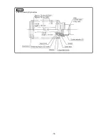
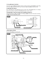
Confirm that the Retaining Ring D15
[21]
groove on the Change Lever
[17]
can be seen inside the gear
cover, and then insert the Retaining Ring D15
[21]
by pushing it into the groove. For easy insertion, use
pliers to insert the Retaining Ring D15
[21]
, while keeping it tilted at an angle of 10 to 20 degrees relative to
the main shaft.
After inserting the Retaining Ring D15
[21]
, check that the Retaining Ring D15
[21]
can rotate smoothly.
(Check also that the Retaining Ring D15 has been fitted correctly.)
Reassembly
Fig. 20


