background image

13

En

Installation and Connections

English

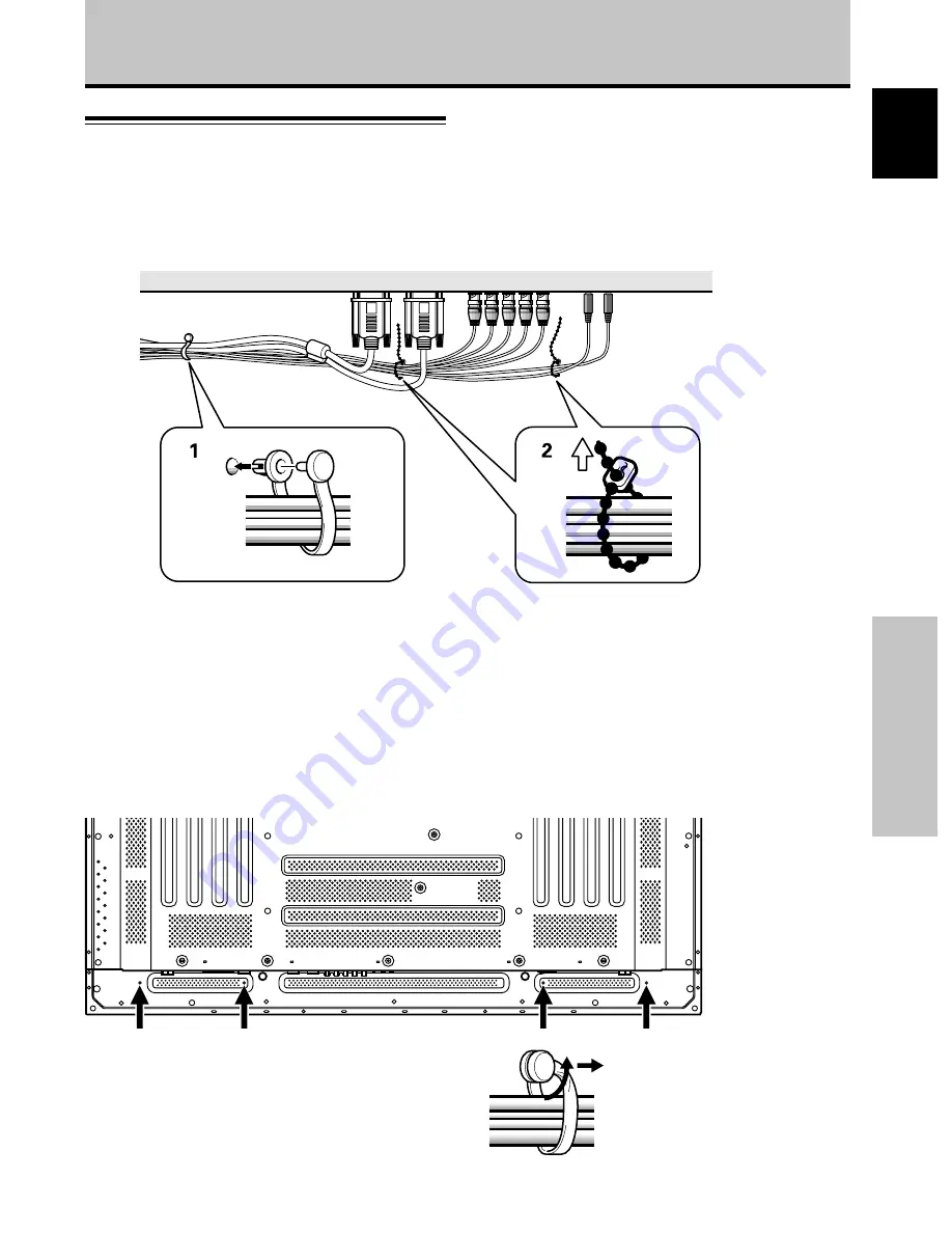
How to Route Cables

Speed clamps and bead bands are included with this unit
for bunching cables together. Once components are
connected, follow the following steps to route cables.

1

Organize cables together using the provided
speed clamps.

Insert 

1

 into an appropriate hole on the rear of the

unit, then snap 

2

 into the back of 

1

 to fix the clamp.

Speed clamps are designed to be difficult to undo
once in place. Please attach carefully.

To attach the speed clamps to the main unit

Connect the speed clamps using the 4 holes marked with •
below, depending on the situation.

To remove speed clamps

Using pliers, twist the clamp 90° and pull it outward.
In some cases the clamp may have deteriorated over
time and may be damaged when removed.

* As viewed from the rear of the display.

Installation and Connections

1

2

2

Bunch separated cables together and secure
them with the provided bead bands.

Note

Cables can be routed to the right or left.

Summary of Contents for CMP5000WXJ

Page 1: ...the instructions written in either English or French For customers in Japan please use and refer to the instructions written in Japanese Les caractéristiques les spécifications d alimentation les accessoires et d autres informations diffèrent d un pays à l autre Si vous vivez au Canada ou aux États Unis reportez vous aux instructions en français ou en anglais Si vous vivez au Japon reportez vous a...

Page 2: ...ails consult your local retail dealer Français Cet appareil est conçu pour une utilisation comme moniteur d affichage d ordinateur La carte vidéo optionnelle est nécessaire si vous souhaitez regarder d autres signaux sur ce moniteur Pour plus de renseignements consultez votre revendeur 日本語 本機はパソコン用モニターとして設計されています 本機でビデオ信号を見るときは 別売りのビデオカードが必要です 詳しくは お買い求めの取り扱い店にお問い合わせください ...

Page 3: ... the future Notes on Installation Work This product is marketed assuming that it is installed by qualified personnel with enough skill and competence Always have an installation specialist or your dealer install and set up the product HITACHI cannot assume liabilities for damage caused by mistake in installation or mounting misuse modification or a natural disaster Note for Dealers After installat...

Page 4: ...ditions The thinner lighter design coupled to high endurance construction greatly broadens the range of possible installation locations and styles High reliability for commercial applications The is provided with features giving it high dependability in commercial applications including the ability to suppress peak luminance in accordance with the viewing program and to change the cooling fan s sp...

Page 5: ... Selecting an Input Source 16 Screen Size Selection 18 Partial Image Enlargement POINT ZOOM 19 Automatic Power OFF 20 Display Panel Adjustments 21 Adjusting the Picture Quality 21 Adjusting the Image Position and Clock Automatic Adjustment 22 Manual Adjustment of Screen Position and Clock 23 Other Operations 24 Rewriting the Input Display INPUT LABEL 24 Power Control Function 25 AUTO FUNCTION 25 A...

Page 6: ...e monitor If you drop water or a foreign substance on to the monitor it may cause fire or an electric shock If it happens turn off the monitor and disconnect the power plug from the mains and ask service center for instruction Do not put the monitor on an unstable place If you put the monitor on an uneven or unstable place it may fall down and you may be injured Put the monitor on a flat surface s...

Page 7: ...may cause serious injury or damage to your property CAUTION Disconnect the power plug from the mains when you move the monitor Moveing the monitor without disconnecting the power plug from the mains may damage the cord and cause a fire or electric shock You are advised to move the monitor with two persons Handle with care when you move the monitor particularly take care of glass screen When you di...

Page 8: ...sh them at appropriate intervals of time Turn down the contrast and brightness controls How to clean the monitor Before cleaning the monitor turn off the monitor and disconnect the power plug from the mains When cleaning the monitor do not spray directly the screen or cabinet with cleaner Use a clean dust free dry and soft cloth If it is not enough then use a cloth with non alcoholic or non ammoni...

Page 9: ...ed that following conditions are met Video inputs The input signal amplitude must not exceed the specified level CAUTION Changes or modifications not expressly approved by the party responsible for compliance could void the user s authority to operate the equipment Declaration of Conformity According to 47CFR Part 2 and 15 for Class B Personal Computers and Peripherals and or CPU Boards and Power ...

Page 10: ...llation of the plasma display and connections to a wide variety of components The section Setting Up the System starting on page 14 covers the necessary on screen menu settings to establish correct linkage between the plasma display and connected components Depending on the connections made this section may or not be necessary The remainder of the sections in this manual is dedicated to the basic ...

Page 11: ...re Proceeding Checking Supplied Accessories Check that the following accessories were supplied 1 Power cord 2 Remote control unit 3 AA R6 batteries x 2 4 Speed clamps x 2 5 Bead bands x 2 Before Proceeding USER S MANUAL ...

Page 12: ...age 16 4 INPUT button Press to select input page 16 5 MENU button Press to open and close the on screen menu pages 14 to 26 6 ADJUST 5 3 2 buttons Use to navigate menu screens and to adjust various settings on the unit Usage of cursor buttons within operations is clearly indicated in the on screen display pages 14 to 26 7 SET button Press to adjust or enter various settings on the unit pages 14 to...

Page 13: ...e the remote control Do not use the remote control unit in a location subject to direct sunlight heat radiation from a heater or in a place subject to excessive humidity When the remote control unit s batteries begin to wear out the operable distance will gradually become shorter When this occurs replace all batteries with new ones as soon as possible Inserting the batteries in the remote control ...

Page 14: ... that the connection made corresponds to the format of the signal output from the connected component pages 9 to 11 If you are having difficulty with operation of the remote control unit The remote control unit may not operate if there are objects placed between it and the display Operational distance will gradually become shorter as the batteries begin to wear out replace weak batteries with new ...

Page 15: ...tput jack of components connected to INPUT1 or INPUT2 to this unit page 11 0 AUDIO OUTPUT Stereo mini jack Use to output the audio of the selected source component connected to this unit to an AV amplifier or similar component page 11 1 2 3 4 5 6 7 89 0 L IN OUT CONTROL COMBINATION IN OUT RS 232C ANALOG RGB ANALOG RGB INPUT1 OUTPUT G B R HD VD ON SYNC H V SYNC Ô 75 2 2 Ω kΩ INPUT INPUT1 2 OUTPUT A...

Page 16: ... sure to attach in 4 or more locations above and below left and right of the center line Use bolts that are long enough to be inserted 1 2 inch 12 mm to 11 16 inch 18 mm into the main unit from the attaching surface for both a holes and b holes Refer to the side view diagram below As this unit is constructed with glass be sure to install it on a flat unwarped surface CAUTION Because this unit weig...

Page 17: ...jack Connection to a personal computer Connection method differs depending on the computer type When connecting please thoroughly read the computer s instruction manual Before making connections be sure to make sure that the personal computer s power and this unit s main power is off For the PC input signals and screen sizes that this unit is compatible with please refer to supplement 1 page 31 Co...

Page 18: ...GB INPUT1 OUTPUT With this unit it is possible to output the video signal to an external monitor or other component from the OUTPUT INPUT1 terminal Note A video signal will not be output from the OUTPUT INPUT1 terminal when the main power of this unit is off or in standby To an external monitor Connection of G ON SYNC analog RGB source Make G ON SYNC connections for a personal computer with output...

Page 19: ...omponent s power and the unit s main power is off Connecting the speakers This unit is equipped with speaker output jacks for connection to the speaker system not supplied specially designed for use with this unit Refer to the illustrations below when making connections to the speaker terminals on this unit 10 mm Note When making speaker connections be sure to match the polarities and of the speak...

Page 20: ...wer supply voltage other than that indicated AC 100 120 V 50 60 Hz as this may cause fire or electric shock For the plasma display a three core power cord with a ground terminal is used for efficiency protection Always be sure to connect the power cord to a three pronged grounded outlet and make sure that the cord is properly grounded If you use a power source converter plug use an outlet with a g...

Page 21: ...amp Speed clamps are designed to be difficult to undo once in place Please attach carefully To attach the speed clamps to the main unit Connect the speed clamps using the 4 holes marked with below depending on the situation To remove speed clamps Using pliers twist the clamp 90 and pull it outward In some cases the clamp may have deteriorated over time and may be damaged when removed As viewed fro...

Page 22: ...ollow the procedure described below and make settings as they apply to the type of components connected Screen Mode setup Note These settings are required only when using the following input signal refresh rates 1 31 5 kHz horizontal 60 Hz vertical 2 48 4 kHz horizontal 60 Hz vertical or 56 5 kHz horizontal 70 Hz vertical No manual setup is necessary for signals with other refresh rates since adju...

Page 23: ... A I NP UT I NP UT 1 L E B L A MAIN MENU INPUT1 3 Press 5 to select CLAMP POSITION SELECT CHANGE EXIT SET MENU PICTURE SCREEN SET UP OPTION NT S E T T I N CL AMP POWE R G OF F P S I T I ON O M NAGEME A I NP UT I NP UT 1 L E B L A V GA A U TO MAIN MENU INPUT1 4 Press SET to select LOCKED SELECT CHANGE EXIT SET MENU PICTURE SCREEN SET UP OPTION NT S E T T I N CL AMP POWE R G OF F P S I T I ON O M NA...

Page 24: ...nal input will cause the menu screen to turn off If the input computer signal is not supported by the display the following message will be displayed 0 8 5 5 1 2 6 8 4 k H z f V 1 7 1 7 H z f H P O U SUP N S R ED T I NAL G CAU I O N T FUL L I NPUT 1 X 0 2 0 k H z f V 7 7 1 5 H z f H T OU N O A R F G E CAU I O N T FUL L I NPUT 1 4 Use VOLUME on the remote control unit to adjust the volume If no aud...

Page 25: ...tomatically canceled about 8 minutes after the button is pressed and the volume level is adjusted to the minimum level Press VOLUME or VOLUME to adjust the volume at a desired level To confirm display settings DISPLAY Press DISPLAY on the remote control unit The currently selected input screen size and refresh rates will be displayed for about 3 seconds O D BY T DOT I NPUT 1 0 6 0 4 6 0 8 4 0 k H ...

Page 26: ...en sizes described in the table on this page Press SCREEN SIZE to select the size The screen size changes each time SCREEN SIZE is pressed as follows Consult the table Computer Signal Formats Supported page 31 for information regarding screen sizes supported by each signal format Notes When the PARTIAL or FULL setting is used to display a non wide screen 4 3 picture fully on a wide screen a portio...

Page 27: ...aken for three seconds or more the display screen will disappear SET or 5 2 3 can be pressed again if desired to change the zoom ratio or display position 4 Press the remote control unit s POINT ZOOM once again to cancel the point zoom operation The point zoom function will also be canceled whenever the input signal changes the menu screen is displayed or the INPUT changes Note Whenever point zoom...

Page 28: ...N AU T O S E T T I N CL AMP POWE R G OF F P S I T I ON O M NA GEME A I NP UT I NP UT 1 L E B L A V GA NT MAIN MENU INPUT1 When using INPUT 2 PICTURE SCREEN SET UP OPTION V GA AU T O S E T T I N CL AMP A UTO POWE R G OF F OF F P S I T I ON O I NP UT I NP UT 2 L E B L A MAIN MENU INPUT2 4 Press SET to confirm selection of the POWER MANAGEMENT or AUTO POWER OFF When OFF is selected the display will c...

Page 29: ...s PICTURE mode adjustment items Below are brief descriptions of the options that can be set in the PICTURE mode CONTRAST Adjust according to the surrounding brightness so that the picture can be seen clearly BRIGHT Adjust so that the dark parts of the picture can be seen clearly R LEVEL Adjust the amount of red in the picture G LEVEL Adjust the amount of green in the picture B LEVEL Adjust the amo...

Page 30: ...erform this adjustment individually for each input function INPUT 1 INPUT 2 and each signal type Press AUTO SET UP on either the main unit or remote control unit Optimum settings may not be possible for low luminance and certain other kinds of signals In this case following the instructions in the following section Manual Adjustment of Screen Position and Clock to make more precise adjustments AUT...

Page 31: ...ow are brief descriptions of the options that can be set in the SCREEN mode POSITION H POSITION Adjust the picture s position to the left or right V POSITION Adjust the picture s position upward or downward CLOCK PHASE CLOCK Adjust letter breakup or noise on the screen This setting adjusts the unit s internal clock signal frequency that corresponds to the input video signal PHASE Adjust so that th...

Page 32: ...E B L A T E S RE D N E A E C A S P MAIN MENU INPUT1 5 Press 2 3 5 to select the first desired character here C then press SET to confirm repeat this step to input up to eight desired characters SELECT SET EXIT SET MENU BACK SPACE J M K L B C D E F G H W Z X Y N O P Q R S T V U 9 0 1 2 3 4 5 6 8 7 I NP UT I NP UT 1 L E B L A T E S RE E C A S P D N E A C I MAIN MENU INPUT1 Usable characters include ...

Page 33: ...ARD setting but at a even lower levels of power consumption MODE 2 fixes the screen brightness regardless of the input signal This is effective at reducing panel deterioration due to screen burning 4 Following completion of settings press MENU to return to normal screen display Note The POWER CONTROL setting affects all input sources AUTO FUNCTION This display is equipped with an optional AUTO FUN...

Page 34: ...O OUT The signal level produced at the AUDIO OUT jack can be set to FIXED or VARIABLE linked to the VOLUME as desired 1 Press MENU The onscreen menu will be displayed MAIN MENU INPUT1 SELECT ENTER EXIT SET MENU PICTURE SCREEN SET UP OPTION 0 6 0 6 0 6 0 0 0 CONT RAST 0 BR R L EV EL I GHT G L EV EL B L EV EL H E NHANCE V E NHANCE R S ET E 2 Press 2 3 to select OPTION SELECT CHANGE EXIT SET MENU PIC...

Page 35: ...ubleshooting What may at first seem to be an malfunction may be remedied with a quick check Please check to see if a warning is displayed on the screen If displayed refer to the table below and check the mode If there is no display check to see if the problem is listed on page 28 The problem may also be caused by something other than this unit so please also check the other components being used s...

Page 36: ...tions of image appear to be losing intensity Speckles or noise appears on screen Stripes appear on the screen Operation is not possible Sound is heard from inside the unit Fan isn t moving Fan speed changes Check the input signal compatibility chart page 31 Is the correct screen size selected pages 18 22 and 23 Adjust using SCREEN mode on the menu screen page 23 If there is still no improvement th...

Page 37: ...DBY ON is pressed to set the unit to the standby mode the indicator will flash red for several seconds page 16 Other than this if the power turns off by itself or refuses to turn on or if the red indicator conditions flashing a malfunction may be indicated Immediately disconnect the power plug and consult your dealer or a service center Additional Information About the plasma panel s protection fu...

Page 38: ...ay VESA DDC1 2B Output Mini D sub 15 pin socket connector 75 Ω with buffer INPUT 2 Input BNC jack x5 RGB signal G ON SYNC compatible RGB 0 7 Vp p 75 Ω no sync HD CS VD TTL level positive and negative polarity 75 Ω or 2 2 kΩ impedance switch G ON SYNC 1 Vp p 75 Ω negative sync Additional Information Audio Input AUDIO INPUT for INPUT 1 2 Stereo mini jack L R 500mVrms more than 10 kΩ Output AUDIO OUT...

Page 39: ...46 9kHz 53 7kHz 49 7kHz 31 7kHz 48 4kHz 56 5kHz 60 0kHz 60 2kHz 68 7kHz 53 7kHz 64 9kHz 67 7kHz 68 7kHz 61 8kHz 71 7kHz 45 1kHz 48 4kHz 55 5kHz 60 0kHz 64 0kHz 80 0kHz 91 1kHz 75 0kHz 81 3kHz 87 5kHz 93 8kHz 106 3kHz 1024x768 1024x768 1024x768 1024x768 1016x768 984x768 1024x768 960x768 1024x768 640x480 800x600 832x624 852x480 1024x768 1280x768 4 3 NEC PC 9800 NEC PC 9800 852x480 864x480 Apple Maci...

Page 40: ...Supplement 2 Signal assignment of INPUT 1 Mini D sub 15 pin socket connector Input Output 1 2 3 4 5 6 7 8 9 10 11 12 13 14 15 R or CR PR G or Y B or CB PB NC No connection GND GND GND GND DDC 5V GND NC No connection DDC SDA HD or H V SYNC VD DDC SCL NC No connection NC No connection NC No connection 5 1 15 11 6 10 Pin No Apple and Macintosh are registered trademarks of Apple Computer Inc Microsoft...

Page 41: ...ghly After reading please store this manual in a safe place for future reference This plasma display tabletop stand is for use only with the following model CMP5000WX Request an installation specialist to install this unit This company assumes absolutely no responsibility for injuries and damages that may occur due to improper installation and handling Stand pipes left and right interchangable x 2...

Page 42: ...ed general CAUTION WARNING Always use at least two people to perform the installation work Injury could result from dropping heavy objects Use the specified bolts and screws in the specified places and tighten firmly Failure to do this could cause injury if the plasma display falls Avoid installing in locations where the temperature and humidity are excessively high and where contact with water is...

Page 43: ...asma display housing At this point tighten these bolts 1 only until the threads are no longer visible when viewed from t he side you will be unable to attach the display if the bolts are screwed in completely Plasma display Installation bolt 1 M8 x 20 Holes a holes in center of plasma display Installation bolt 1 Plasma display housing Stop screwing down the bolt when the threads are no longer visi...

Page 44: ...tand so that the stand screw holes and the nuts that connect the main display line up correctly The display is a 50 model that weighs approximately 40 kilograms 88 lb and has little depth making the display very unstable For this reason at least two people are required for setup and installation Notes Stand attaching to the Plasma Display Installation bolts 2 M8 x 40 Step 3 Table top stand Slide t...

Page 45: ...e the display by connecting to a wall or standing beam with a strong cord Repeat the same steps in the laterally direction to stabilize the assembly to the left and right Use cord and hooks that are available on the market sold separately 1 2 Installation coordinates for screws used to stabilize the stand to the floor When stabilizing the stand to the floor use M6 with a length above 20 mm 25 32 i...

Page 46: ...b 42 9 kg 94 58 lb When the 50 inch plasma display is attached Main material Surface treatment Steel sheet ABS Dimensions Diagram 774 150 220 339 508 566 1218 774 150 220 1368 566 1218 339 508 Normal use without optional speakers Optional speakers attached to both sides of display Speaker Speaker 38 En ...

Page 47: ... ensure customer safety be sure to design the installation location so that the strength is sufficient to withstand the weight of both the plasma display and the wall mount unit Always use at least two persons for all installations Fully tighten all of the mounting screws as specified in the installation instructions Thank you for purchasing the Hitachi Plasma Display Wall mount Unit To ensure cor...

Page 48: ...In the cases such as The plasma display is loose and vibrates to an extreme degree Mounting screws or parts are loose or missing failure to take appropriate actions can result in injury Perform the following actions immediately whenever a malfunction occurs Turn off the plasma display power switch Disconnect the power plug from the power outlet Surround the area with rope etc to prevent other peop...

Page 49: ... of fully supporting the load of the plasma display 10cm or more 10cm or more 10cm or more Avoid installing in locations where the temperature and humidity are excessively high and where contact with water is possible These can result in fire or electrical shock Installation Location WARNING CAUTION Do not install close to an air conditioner intake or outlet Do not install in locations where there...

Page 50: ...ified places and tighten firmly Failure to do this could cause injury if the plasma display falls Make sure the display fittings and wall mount fittings are firmly engaged Failure to do so could cause the plasma display to fall Do not alter any of the parts And do not use broken parts This could result in injury due to the plasma display falling Always use at least two people to perform the instal...

Page 51: ...triangle Top side of plasma display 7 Fix the bottom of the hardware with the special screws removed at step 1 one on the left and one on the right Special screw M6 5 Attach the wall side hardware to the wall Install the wall side hardware 4 locations symmetrically on the left and right side one at each location from the center of the Because the screws and bolts used to do this are different acco...

Page 52: ...33mm 10 188mm 15 241mm 20 291mm Angle setup This installation hardware allows the display to be directed downwards freely at any angle from the vertical to 25ˇ This adjustment must always be done by 2 people Adjust the angle by rotating the screws at the center top and center bottom of the wall side hardware to the left or right Warning If the angle is increased while you are adjusting the angle u...

Page 53: ...l Steel sheet Surface treatment Black baked paint Products mounted CMP5000WX 59 6 φ10 5 6 23x10 5 314 239 314 239 33 35 150 150 35 35 714 44 455 555 655 496 740 1368 With side speaker 545 465 232 212 410 143 45 44 573 258 54 43 1218 Without side speaker 98 125 25 45 En ...

Page 54: ...x wrench For top right side x 1 For top left side x 1 For bottom x 2 Speaker mounting bolts Flat countersunk head screw x 4 Hexagon socket head screw x 4 Washer M8 ø 25 x 2 Mounting plate For right side x 1 For left side x 1 NOTE Always use the accessory mounting fittings for installation When screws other than those enclosed as accessories are used to install the speakers the speakers may drop of...

Page 55: ...installation position and attach the mounting plate to the inside of the speaker Seal 2 Install the mounting fittings on this unit The illustration shows an example for this unit right side For top side Flat countersunk head screw Mounting plate 1 The top side fittings are different for the right and the left side and they must be matched correctly 2 Install the mounting fittings with bolts at the...

Page 56: ...ax or cleaners They may damage the surface of the cabinet Never use thinner benzine insecticide sprays and other chemicals on or near the cabinets since these will corrode the surfaces When a chemical cloth is used read the cautions for the chemical cloth carefully SPECIFICATIONS Cabinet Enclosed type Used speakers two way method Woofer for low tones Oval cone type Tweeter for high tones 2 5 cm do...

Page 57: ...3 Fax 49 89 991 80 224 Email rplan hitachi eu com Hotline 49 180 551 25 51 12ct min Email HSE DUS Service Hitachi eu com HITACHI EUROPEAB HITACHI EUROPE SRL Box 77 Via T Gulli n 39 S 164 94 KISTA 20147 MILAN SWEDEN ITALY Tel 08 562 711 00 Tel 02 487861 Fax 08 562 711 11 Fax 02 48786381 Servizio Clienti Email csgswe hitachi eu com Tel 02 38073415 Email customerservice italy hitachi eu com HITACHI E...

Reviews: