background image

2. Main Menu (Manual Adjustments)

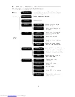
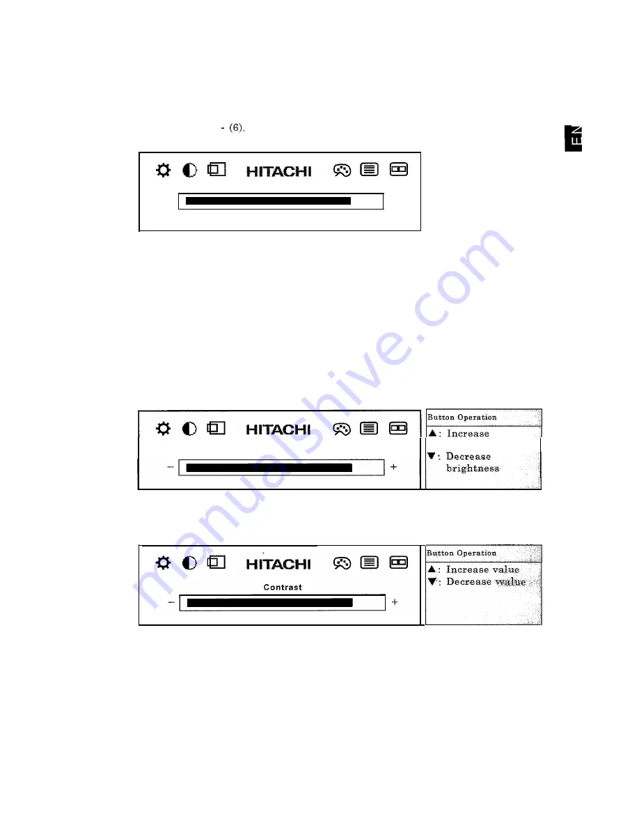
When the MENU button is pressed with the screen being displayed without the OSD

menu showing, the following OSD menu will be displayed. Pressing the menu button

will move the cursor to the next item to adjust.

The icon at the cursor position will change form blue to red and name of the

adjustment will be shown.

After moving through (1)   

 the OSD menu will end if the MENU button is

pressed.

Adjustments

(1) Brightness (2) Contrast (3) Display position (4) Display color

(5) Clock/Phase (6) Management

The OSD menu will automatically end if there is no operation for about 30

seconds.

Press the MENU button for about 2 seconds to end the OSD menu.

(1) 

Brightness adjustment

Select with the MENU button or press the A button with the OSD menu not being
shown to display the brightness adjustment screen. When the A button is pressed,
only the brightness adjustment bar will be shown.

This adjusts the brightness for the backlight.

B r i g h t n e s s

brightness

(2) Contrast adjustment

This adjusts the ratio of the white and black levels.

The adjustment value range

will differ according to the PC.

Button Operation

A : Increase value

 Decrease 


17

Summary of Contents for CML151XW

Page 1: ...hasing Hitachi s Liquid Color Display Please read the User s Manual carefully and store in a safe place along with the guarantee l Please read and make sure you fully understand the safety precautions before use Please keep this User s Manual in a handy location for easy reference ...

Page 2: ......

Page 3: ...15 of the FCC Rules These limits are designed to provide reasonable protection against harmful interference in a residential installation This equipment generates uses and can radiate radio frequency energy and if not installed and used in accordance with the instructions may cause harmful interference to radio communications However there is no guarantee that interference will not occur in a part...

Page 4: ...referably a qualified electrician If there is no alternative to cutting off the mains plug ensure that you dispose of it immediately having first removed the fuse to avoid a possible shock hazard by inadvertent connection to the mains supply Green Yellow Brown to Live to Earth Blue to Neutral Blue to Cord Clamp WARNING THIS EQUIPMENT MUST BE EARTHED IMPORTANT The wires in the mains lead are Colour...

Page 5: ... and during their manufacture Since it is not so far possible to satisfactorily recycle the majority of electronics equipment most of these potentially damaging substances sooner or later enter nature There are also other characteristics of a computer such as energy consumption levels that are important from the viewpoints of both the work internal and natural external environments Since all metho...

Page 6: ...able Cadmium Cadmium is present in rechargeable batteries and in the colour generating layers of certain computer displays Cadmium damages the nervous system and is toxic in high doses The relevant TC0 99 requirement states that batteries the colour generating layers of display screens and the electrical or electronics components must not contain any cadmium Mercury Mercury is sometimes found in b...

Page 7: ...Liquid Color Display Please read the User s Manual carefully and store in a safe place along witfi the guarantee l Please read and make sure you fully understand the safety precautions before use Please keep this User s Manual in a handy location for easy reference ...

Page 8: ......

Page 9: ...olay 10 of Pa La 11 I Pow62 Switch 1 12 B Power Lxmg 12 OSD Operation Button 12 13 I Summalv of Adjust ment Functions 14 OSD Adudment Function s 15 meous Functions 25 ware Technical 26 E Snecificat Ions 26 m Connector Sip 2 7 2 8 29 30 m Possible Causes and 30 1 When you don t know what to do 30 31 alltee and Servicinv 3 1 32 _ B Displa r Placement 32 a JVliscelJ aneous 32 ...

Page 10: ... A Notice Example 11 Shock Caution The A symbol indicates that caution should be taken and within the A is a picture depicting Shock Caution CD Notice Example 1 Disassembly Prohibited In the 8 symbol is an action that must not be done and the picture in this 8 depicts Disassembly Prohibited e Notice Example 31 Unplug Power Cord from Socket In the l symbol is an action that should be taken This 0 i...

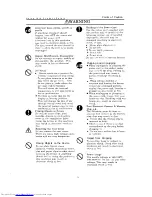
Page 11: ...water pins and paper clips or other metal items on the device If anything should fall in using the product in this condition may result in electrical shock or fire 0 e a 8 8 Handing of the Power Cord Use the power cord supplied with the product and be careful of the following during use If handled improperly the cord may be damaged resulting in electrical shock or fire l Never place objects on it ...

Page 12: ...that are very different in temperature may cause condensation on the outside and internally Using the device in this condition may result in fire or electrical shock Leave the device at the location for a few hours before using Aluminum Electrolysis Condenser The electrolyte condenser used in the AC adapter has a limited life If used past the life span approximately 5 years replace the AC adapter ...

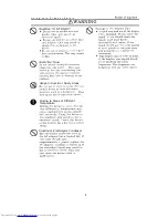
Page 13: ...n adjusting the LCD forward or back Your fingers may get caught and cause injury Eyestrain When continuously looking at the display while working keep the work area lighted at 300 1000 luxes Additionally for every hour of work rest 10 to 15 minutes Continuously looking at the display for prolonged periods will cause accumulated eye fatigue Disposal of this Product When disposing of this product co...

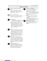
Page 14: ...dapter n R o u t i n e C a r e l Before doing any maintenance of the display insure that the power is OFF 0 Wipe any dirt off with a dry soft cloth If soiled with oil or heavily soiled damp cloth with water or soap wring dry and lightly wipe the soiled areas Remove dust with a vacuum cleaner or a dry cloth If water or soap should get into the display this may cause damage 0 Using benzene or thinne...

Page 15: ...l modes Full color 16 77 million colors display is supported and can be used in a wide range of applications from still screens to moving pictures The interface to the PC is compatible with an analog CRT interface and can be readily used just by connecting to the PC CRT display connector Also DDCBB is supported and is Plug Play compatible Power consumption is approximately 35W and compared to a 17...

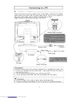
Page 16: ...connector To Personal Computer Power cord J x To AC outlet Power plug DC plug Power connector AWARNING 0 Hold the power plug firmly whenever plugging in or unplugging the power cord from the AC adapter and the wall socket Also make sure that the plug is pushed all the way in l Do not voltage other than shown 100 12OV 200 24OV AC l Do not use power cords other than the one provided with the product...

Page 17: ...iffer according to what version of Windows is being used If this should happen follow the instructions on the screen A E 1 2 3 4 5 6 7 8 9 10 Start up Windows Click Start Setting S and Control Panel C in this order Double click Display in the Control Panel Click the Settings tab Set the Display fields Color pallets etc Click on Details D Click on the Monitor tab Check on Automatically detect Plug ...

Page 18: ...tebook PC usage Human Engineering Guidelines 1988 Labor Science Research Institute l Set the PC display in front of you and adjust to an easy viewing angle l The illumination and brightness of the display should be adjusted appropriately to the surrounding lighting and suppress reflection from the display l Adjust the brightness and contrast for easy viewing l The keyboard and mouse should be plac...

Page 19: ...and right Choose an angle that is most suitable for you ACAUTION 0 When adjusting the angle hold the top left and right edges with both hands and move slowly Using only one hand may cause it to fall l Do not place your hand near the stand when adjusting the LCD stand forward or back Your fingers may get caught and cause injury 11 ...

Page 20: ...ollowing manner Refer to the adjustment functions for details MENU button 0 When the OSD is not being displayed pressing this will display the OSD m e n u 0 This is used with the OSD menu displayed to select various settings 0 If pressed for about 2 seconds when the OSD menu is being displayed the OSD display will end 4 UP button A display 0 This will move the cursor up to the right or increase an...

Page 21: ...hile looking at the OSD menu l If a video signal is not input from the PC the adjustment functions will not operate 0 Please refer to the manual supplied with the PC for display settings on the PC side l The brightness display color OSD position adjustments and language setting are common to all display modes All other settings are only valid for current mode and when the display mode is changed t...

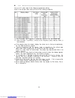
Page 22: ...sition for the splay Adjusts color differential to approximate LCD or CRT Adjusts color balance Adjusts individual brightness of RGB Adjusts individual standard levels for RGB offset values Horizontal Vertical position Phase Clock Contrast and Color Balance adjustments are automatically set Adjusts the number of dot clock numbers in one horizontal period Adjusts sampling timing for input display d...

Page 23: ... settings or set the color balance to your preference settings can be done manually The Japanese display mode will be explained here ORecommended Adjustment Screen Before using the automatic adjustment function display the recommended screen shown below If a screen other than the recommended one is used the adjustment may not be carried out properly Start up Explorer and display the window full sc...

Page 24: ...ge the screen and try again l The automatic adjustments may fail to completely suppress flicker on the screen When this happens save the settings and from the OSD menu manually adjust using the Phase adjustment However screen flicker or blurry text may result from change in the surrounding temperature If this happens redo the setting l The automatic adjustment may fail to properly adjust the scree...

Page 25: ...Display color 5 Clock Phase 6 Management The OSD menu will automatically end if there is no operation for about 30 seconds Press the MENU button for about 2 seconds to end the OSD menu 1 Brightness adjustment Select with the MENU button or press the A button with the OSD menu not being shown to display the brightness adjustment screen When the A button is pressed only the brightness adjustment bar...

Page 26: ...Horizontal position adjustment Adjust the horizontal position of the screen while looking at the display screen H Position I I 3utton Operation Ir Right I Left l Vertical position adjustment Adjust the vertical position of the screen while looking at the display screen V Position V Down I I J II I I I 4 Display color Adjusts the display screen color Selecting Return will move to the following Cloc...

Page 27: ... RGB Adjust Adjusts the brightness of RGB Red Green Blue in When Return is selected you will return to Adjustment menu detail the previous Display Color The following menu is shown when a color is selected The following screen is when red is selected I Restriction 0 Color balance should be done after contrast adjustments are completed 19 ...

Page 28: ... following is when G is selected Q cc Q I EHzMEl Green I Button Operation A Raises the standard level of color selected V Lowers the standard level of color selected 1 MENU Set Restriction 0 The black level should be adjusted after the contrast adjustments are completed 5 Clock Phase Adjustment Adjusts the number of dot clocks within a horizontal synch Adjusts the sampling timing for the input dis...

Page 29: ...t Adjusts the number of dot clocks within one horizontal synch If the clock is not adjusted properly the screen will drift or vertical stripes may be generated according to the screen being displayed If this happens adjust the clock while the screen is drifting or with the vertical stripes being displayed Clock v Decrease value I I I I I Screen Drift Vertical Stripes Example E 21 ...

Page 30: ...er and text blur may result after adjustments due to the surrounding temperature When this happens redo the adjustments Before doing this adjustment complete a Clock Adjustment first Q Q Q I F3ElEl Phase Button Operation V Decrease value Example of blurred text Example of screen flicker ABCDEFGHIJKLMNOPQRST _ _ _ UVWXYZ _ _ _ _ _ _ _ _ _ _ _ _ ABCDEFGHIJKLMNOPQRST _ _ _ _ _ _ _ _ _ _ _ UVWXYZ 22 ...

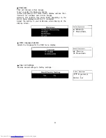
Page 31: ...ion horizontal sync frequency and vertical sync frequency l OSD Position Adjustment Changes the OSD display position When Return is selected you will return to the previous Management menu When the horizontal position adjustment is selected the following screen will be shown Adjust the screen horizontal position while looking at the display screen Q Q Q HtTAcHl CJ El m H Position A Move right up V...

Page 32: ... this function may cause flicker depending on the screen being displayed and the PC connected Adjust the setting to your preference while looking at the display screen A Move up I Move down 0 OSD Language Selection Selects the language for the OSD menu display 0 Clear All Settings Returns saved settings to factory settings V Move down Button Operation I A V Move cursor 1 MENU Set 24 ...

Page 33: ... a sync signal it will automatically decrease power consumption and the SAVE lamp located on the right side of the screen will light orange To use the PC energy saving functions refer to the manual that came with the PC E l Plug Play Function This device supports DDC2B Display Data Channel 2B standards and is Plug Play compliant Refer to the PC manual when connecting to a PC and using the Plug Pla...

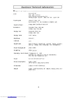
Page 34: ...rizontal 304 1 mm Vertical 228 1 mm Display colors 16 77 million Brightness 200cd m2 Contrast 35O l Adjustments OSD functions brightness contrast display position setting display color clock phase and management Power management VESA DPMS Plug Play VESA DDCBB Operating Environment Temperature 5 35 C Humidity 20 80 Rh or less no condensation Max dry heat temperature 25 C Power AC lOO 12OV 200 240V ...

Page 35: ... l s l 15 pin mini D SUB connector Chart from display connector 13 1 HSYNC 1 Horizontal Sync Signal 1 Input 14 1 VSYNC 1 Vertical Sync Signal 1 Input 1 15 1 SCL 1 DDC Clock Input 1 l This signal is valid for DDC2B compatible PCs 27 ...

Page 36: ...ove when changing the PC resolution and color settings If set to a video mode not listed above the screen may become distorted or not display properly 0 Also if set to a video mode not listed above and even when the display appears normal the OSD adjustments may not function properly l If connected to a notebook computer and used with the built in display the display may work properly according to...

Page 37: ...If the time the power in on is more than the above the life span will become accordingly shorter 2 The LCD module has exceeded it s life span when the brightness become about half from the original time of purchase The life span will change with the length of use and brightness setting AWARNING The electrolyte condenser used in the AC adapter has a limited life span If used over the intended life ...

Page 38: ...Is the display cable properly Remedy 1 Please connect the display cable connected properly _ I connected Has the PC been setup properly Refer to the section on setting up the PC and properly setup the PC l Screen Position Offset Possible Cause Has the screen position been properly adjusted Remedy 1 Use the automatic adiustments or use the OSD function to properly adjust the horizontal and vertical...

Page 39: ...arantee for terms and the period Please consult with your dealer for repairs after the guarantee period has expired n The guarantee will have the dealer s address information recorded at the time of delivery Please make sure to confirm the contents and store in a safe place 31 ...

Page 40: ...ll lead to malfunctions I M i s c e l l a n e o u s l When not in use use a cover to prevent dust from getting in l Do not press the display area or apply unnecessary stress when transporting The LCD display area may break l The surface of the LCD display area is easily scratched and should not be pressed hit or rubbed with hard objects such as pencils or ballpoint pens l Because of the characteri...

Page 41: ...3 Fax 49 89 991 80 224 Email rplan hitachi eu com Hotline 49 180 551 25 51 12ct min Email HSE DUS Service Hitachi eu com HITACHI EUROPEAB HITACHI EUROPE SRL Box 77 Via T Gulli n 39 S 164 94 KISTA 20147 MILAN SWEDEN ITALY Tel 08 562 711 00 Tel 02 487861 Fax 08 562 711 11 Fax 02 48786381 Servizio Clienti Email csgswe hitachi eu com Tel 02 38073415 Email customerservice italy hitachi eu com HITACHI E...

Reviews: