background image

-11-


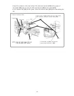
• Carburetor ass’y


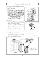
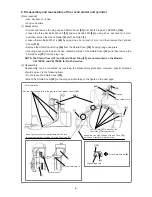
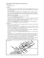
3. Disassembly and reassembly of the carburetor ass'y 

[Tools required] 

• Hex. bar wrench (4 mm) 

• Pliers 

(1) Disassembly 

• Clamp both ends of the Insulator Clip 

[147]

 with pliers. The Insulator Clip 

[147]

 opens wider. Remove 

the Insulator Clip 

[147]

 from the groove of the Carburetor Insulator 

[149]

 and move it toward the 

Insulator Plate 

[148]

• Pull out the Carburetor Insulator 

[149]

 from the Cylinder 

[146]

. Be careful not to break the insulator. 

• Remove the Choke Button 

[191]

 and Choke Rod Rubber 

[192]

 from Carburetor Ass'y (C3M) 

[151]

• Lift up the Carburetor Bracket 

[181]

 and remove the Throttle Rod 

[135]

 from Carburetor Ass'y (C3M) 

[151]

 and the Throttle Lever 

[134]

• Remove the Fuel Pipes 

[105] [137]

 from Carburetor Ass'y (C3M) 

[151]

• Remove Fuel Pipe (FKM) 

[150]

 from the elbow joint. 

• Loosen the two Bolts M5 x 55 

[195]

 by using a hex. bar wrench (4 mm), and then remove the 

Carburetor Insulator 

[149]

, Insulator Plate 

[148]

, two Square Nuts (B) M5 

[167]

, Carburetor Ass'y 

(C3M) 

[151]

, Carburetor Packing 

[180]

, and Carburetor Bracket 

[181]

• Remove the Fuel Pipe 

[166] 

from Carburetor Ass'y (C3M) 

[151]

 and the Carburetor Bracket 

[181]

• Remove Fuel Pipe (FKM) 

[150]

 from Carburetor Ass'y (C3M) 

[151]

(2) Reassembly 

Reassembly can be conducted by reversing the disassembly procedure. However, special attention 

should be given to the following items. 

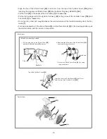
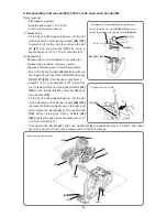
• Subassemble the parts of the Carburetor Insulator 

[149]

 as shown in the figure below before mounting 

the Carburetor Insulator 

[149]

 on the Cylinder 

[146]

. Make sure the throttle valve and choke valve of 

Carburetor Ass'y (C3M) 

[151]

 move smoothly after subassembly. 

• Fit the lip portion of the Carburetor Insulator 

[149]

 along the groove of the Insulator Plate 

[148]

 when 

mounting the Carburetor Insulator 

[149]

 on the Insulator Plate 

[148]

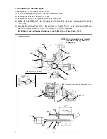
• Be careful not to bend the Fuel Pipes 

[105] [137] [150] [166]

. For details, see “4. Connection of the 

fuel pipes.” 

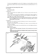
• For reassembly of the Throttle Rod 

[135]

, first insert its tip into the throttle valve of Carburetor Ass'y 

(C3M) 

[151]

, and then fit the rod to the Throttle Lever 

[134]

 while pulling the Throttle Lever 

[134]

• Apply 0.1 to 0.2 g of Alvania Grease RL3 to the sliding portions of the Choke Button 

[191]

 and Choke 

Rod Rubber 

[192]

 (in the range of 16 to 20 mm from the end of the Choke Button 

[191]

). 

• Orient the Choke Button 

[191]

 and Choke Rod Rubber 

[192]

 correctly. Insert Cleaner Box (A) 

[189]

 into 

the slit portion of the Choke Rod Rubber 

[192]

 when reassembling Cleaner Box (A) 

[189]


[195]


[149]


[147]


[148]


[151]


[180] 

[181]

[146]


Ends 

[167]


Subassemble and mount to the cylinder. 

[166]

[150]

Summary of Contents for CM 75EAP

Page 1: ...onal Sales Division TROUBLESHOOTING GUIDE 1 1 Troubleshooting and correction 1 REPAIR GUIDE 3 1 Precautions on maintenance inspection and repair 3 2 Inspection criteria for each section and consumable parts 3 CONTENTS Page LIST Nos CM 75EAP F070 CS 75 EBP F071 Sep 2014 C ...

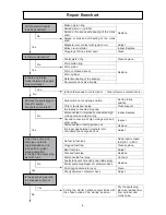
Page 2: ...ected high voltage cord Repair or replace Disconnected or faulty ignition coil ass y Replace Large gap between the magneto rotor circumference and ignition coil ass y Adjust The spark plug does not become wet with fuel after repeated starting operation No fuel in the fuel tank Add properly mixed fuel 25 1 to 50 1 Clogged fuel filter Clean or replace Faulty fuel pipe Adjust replace or connect Fault...

Page 3: ...eplace Faulty carburetor ass y Adjust clean or replace Excessive fuel consumption Clogged air cleaner Clean Poorly adjusted carburetor ass y Adjust Abnormal vibration Improper wheel mounting Mount properly Loose tightening of handle and other parts Check and firmly tighten the loose parts Bent or broken wheel Replace with a new one Engine is running but the wheel hardly moves or is slow Loose belt...

Page 4: ... 1 Accelerating performance Smooth acceleration Gap between magneto rotor and ignition coil ass y 0 2 to 0 4 mm Spark plug NGK BPMR7A Gap between spark plug electrodes 0 6 to 0 7 mm Diamond cutter dimensions 305 mm in outside dia 20 mm in hole dia 355 mm in outside dia 20 mm in hole dia A diamond cutter of 25 4 mm in hole dia is available when using the accessory adapter collar Cut off wheel dimen...

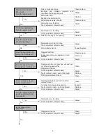
Page 5: ...oil Replace Improper gap between magneto rotor circumference and ignition coil Adjust No fuel in fuel tank Add properly mixed fuel 25 1 to 50 1 Clogged fuel filter Clean replace Bent fuel pipe Adjust Cracked fuel pipe Replace Disconnected fuel pipe Connect Faulty tank vent hole tank cap inside plug Replace Faulty pump diaphragm of carburetor ass y Dirt clogged carburetor ass y Clean Poorly adjuste...

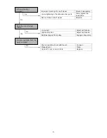
Page 6: ...air cleaner Poorly adjusted carburetor ass y Adjust Faulty carburetor ass y pump diaphragm Replace Dirt clogged carburetor ass y Clean Dirt clogged high speed fuel line of the carburetor ass y Clean Air intake from the packing section Inspect Faulty carburetor ass y pump diaphragm Replace Poorly adjusted carburetor ass y Adjust Revolutions low for idling Adjust Poorly adjusted carburetor ass y Clo...

Page 7: ...off wheel Replace Loose belt Adjust belt tension High belt tension Adjust belt tension Belt disengaged from pulley Engage adequately Poor connection of joint with faucet Connect Clogged joint Clean Hose of 14 mm or less in bore Replace Is there abnormal vibration Is water supplied from the water supplier Does the cut off wheel rotate No Yes Yes No No ...

Page 8: ...c Open the throttle by pulling the Throttle Lever 134 d Pull the starter handle several times 2 Insert Spark Plug Ass y BPMR7A 142 into the Plug Cap Cord 24 and place the electrodes in contact with the metallic portion of the engine Under these conditions set the Stop Switch 196 to the startup position and pull the starter handle 3 When the above steps are all completed normally the electrodes of ...

Page 9: ...Filter 194 in order to remove dust Pat the Paper Filter 193 or apply compressed air from the bottom of the paper filter to remove dust NOTE Never wash the Paper Filter 193 3 Reassembly Reassembly can be conducted by reversing the disassembly procedure However special attention should be given to the following items Insert the slit portion of the Choke Rod Rubber 192 into Cleaner Box A 189 For deta...

Page 10: ...he Shield Cover 25 from the plug cap NOTE The Shield Cover 25 and Shield Cover Ring 26 are not mounted on the Models CM 75EAP and CM 75EBP for North America 2 Reassembly Reassembly can be conducted by reversing the disassembly procedure However special attention should be given to the following items Do not reuse the Shield Cover 25 Mount the Shield Cover 25 on the plug cap according to the figure...

Page 11: ... cord terminal and the terminal retaining rib of the Fan Guide 7 For easier reassembly of the Recoil Starter 8 put the Recoil Starter 8 on its mounting position pull the starter handle and then return it into position 1 Put the plug cap on the Shield Cover 25 and fold the Shield Cover 25 into two 25 Bend here Plug cap 2 Bend and caulk five tabs of the Shield Cover 25 by using the long nose pliers ...

Page 12: ... y C3M 151 2 Reassembly Reassembly can be conducted by reversing the disassembly procedure However special attention should be given to the following items Subassemble the parts of the Carburetor Insulator 149 as shown in the figure below before mounting the Carburetor Insulator 149 on the Cylinder 146 Make sure the throttle valve and choke valve of Carburetor Ass y C3M 151 move smoothly after sub...

Page 13: ...Fit the Insulator Clip 147 into the groove of the Carburetor Insulator 149 when reassembling the clip 135 191 192 134 151 Throttle valve Choke valve 192 Apply 0 1 to 0 2 g of Alvania Grease RL3 to the sliding portions of the Choke Button 191 and Choke Rod Rubber 192 NOTE Orient the Choke Button 191 and Choke Rod Rubber 192 correctly Fit Cleaner Box A 189 to the slit portion when mounting Cleaner B...

Page 14: ...FKM 150 5 The projections of Fuel Pipe Pink 106 and the Fuel Pipe 137 from the Return Grommet 113 and Fuel Grommet 112 should be 100 to 105 mm and 70 to 75 mm respectively NOTE Do not mix up the pipes to be inserted into the Priming Pump Comp 104 Fuel pipe connection 104 151 106 137 148 NOTE Do not mix up the positions of the Fuel Pipe 137 and Fuel Pipe 105 Thread the Fuel Pipe 105 through the hol...

Page 15: ...pply 0 1 to 0 3 g of Chemiseal L 391 Chemitech Inc to the bolt portions of the Spring Holders 60 140 or the female threads of Nut M6 47 and Long Nut M6 116 Fit the tip of a flat blade screwdriver into the slot of the bolt portion of the Spring Holders 60 140 to prevent bolt rotation as shown on the right and firmly tighten the Nut M6 47 and Long Nut M6 116 without turning the Spring Holders 60 140...

Page 16: ...M12 43 NOTE The Clutch 36 screwed into the Crank Shaft 1 is left hand threaded Do not remove Spark Plug Ass y BPMR7A 142 from the Cylinder 146 Set the Decomp 144 to the OFF position pulled to the near side 2 Reassembly Reassembly can be conducted by reversing the disassembly procedure However special attention should be given to the following items Degrease the female threads of the Clutch 36 and ...

Page 17: ...ease the tapered portion of the Magneto Rotor 14 and the threaded and tapered portions of the Crank Shaft 1 before mounting the Magneto Rotor 14 Adjust the gap between the Magneto Rotor 14 and Ignition Coil Ass y 23 when either is disassembled according to 8 Adjustment of gap between the magneto rotor and ignition coil ass y Turn the Magneto Rotor 14 clockwise around the Crank Shaft 1 for reassemb...

Page 18: ...figure 1 Connect the connector of the Cord 21 to the Ignition Coil Ass y 23 2 Connect the Earth Cord 11 to Crank Case A 6 using the Bolt M4 x 10 12 3 Fit the Stop Switch 196 to the Rear Handle Set 114 with the 1 mark on the left side 4 Connect the connectors of the Cord 21 and Earth Cord 11 to the connectors of the Stop Switch 196 5 Place the Switch Cover 197 on the Stop Switch 196 NOTE Do not get...

Page 19: ...egrease the threaded holes of the Cylinder 146 Crank Case A 6 and Crank Case B 44 before remounting the Muffler 124 Temporarily secure the Muffler 124 with the two Bolts M6 x 20 126 and two Bolts M6 x 50 123 and then firmly tighten all the bolts Do not reuse the Bolts M6 x 20 126 and Bolts M6 x 50 123 11 Disassembly and reassembly of the water supplier Tools required Hex bar wrench 5 mm Socket wre...

Page 20: ...168 Replace the bolts with new ones Degrease the threaded holes of Crank Case A 6 and Crank Case B 44 before reassembling the Cylinder 146 Do not reverse the orientation of Cylinder Packing C 169 Mount it according to the shape of the exhaust port Be careful not to damage the cylindrical surface of the Cylinder 146 when disassembled Remove carbon dust from the exhaust port and combustion chamber a...

Page 21: ...gasoline Follow the steps below to insert the Piston Pin 173 See the following figure Reassembly of the piston a Mount the jig J 381 on the Piston 51 5 172 and fit an extra hex socket hd bolt M6 into the pushing end of the Piston Pin 173 b Mount Needle Bearing A 2 on the connecting rod small end and cover it with the Piston 51 5 172 Align the triangular arrow on top of the Piston 51 5 172 with the...

Page 22: ...ston Piston and piston rings 170 172 173 171 2 Pin extracting bolt Round bar 11 8 mm in diameter borer 12 mm in diameter etc Circlip mounting groove 2 Hex socket hd bolt M6 173 Connecting rod small end Connecting rod small end ...

Page 23: ... the Crank Case Packing 3 Do not reuse the four Bolts M5 13 Apply 50 to 100 mg of Piloknock Universal No 0 JX Nippon Oil Energy between the lips of the Oil Seal 5 Carefully clean the Crank Shaft 1 by using gasoline before mounting Before mounting Crank Case A 6 and Crank Case B 44 fully degrease their threaded holes Mount them without pinching Fuel Pipe FKM 150 Assemble the Crank Case Packing 3 by...

Page 24: ...e However special attention should be given to the following items Press fit the Spindle Collar 86 to the Spindle 84 until it contacts the end surface Be careful not to bend the Spindle Collar 86 Orient the Spindle Collar 86 so that its smaller diameter side faces the Arm 63 When inserting Pulley B 51 and the Wheel Washer 85 into the Spindle 84 align the width across flats of Pulley B 51 and Wheel...

Page 25: ...tention should be given to the following items Do not reuse the removed Ball Bearings 6203DD 53 2 pcs Mount the Felt 55 Ball Bearing 6203DD 53 felt side BB Collar 54 Ball Bearing 6203DD 53 retaining ring side Spindle 84 and Retaining Ring 52 to the Arm 63 in this order NOTE Push the outer ring of Ball Bearing 6203DD 53 to press fit it into place When press fitting the Ball Bearing 6203DD 53 retain...

Page 26: ...er Supply Joint A 82 and Water Supply Joint B 74 2 Reassembly Reassembly can be conducted by reversing the disassembly procedure However special attention should be given to the following items Insert the Water Supply Hoses 50 76 until they contact the end faces To secure Water Supply Joint A 82 and Water Supply Joint B 74 insert the Nozzle Bolt 77 into the hole of the Wheel Guard 80 by using long...

Page 27: ...ix up the mounting positions of Handle W 72 Water Supply Joint A 82 Water Supply Joint B 74 and the Stopper Rubber 65 NOTE Note that the Models CM 75EAP and CM 75EBP have different Stopper Rubber 65 mounting positions 50 50 80 72 65 69 74 50 Model CM 75EAP Model CM 75EBP ...

Page 28: ... Handle 117 Lower Guard 202 Front Foot Holder 204 and Front Foot Plate 206 Remove the two Front Foot Rubbers 205 from the Front Foot Holder 204 Loosen the four Bolts M5 x 12 62 by using a hex bar wrench 4 mm and remove the Muffler Guard 203 2 Reassembly Reassembly can be conducted by reversing the disassembly procedure However special attention should be given to the following items Fit the pawls ...

Page 29: ...109 by using a Phillips screwdriver and remove the Air Vent Cap 110 and Inner Cap B 111 Loosen the Tapping Screw D4 x 25 107 by using a Phillips screwdriver and remove the Trigger Lockout 131 and Trigger Lockout Collar 130 Push the Trigger Lockout 131 towards the Throttle Lever 134 and pull it out to remove For details see the figure on the next page NOTE The Rear Handle Set 114 cannot be disassem...

Page 30: ...he Throttle Lever Spring 133 must be positioned behind the Trigger Lockout 131 as shown below Press fit Inner Cap B 111 into the Rear Handle Set 114 by using the jig J 382 inner cap jig A and inner cap jig B For details see the figure on the next page Throttle lever and trigger lockout 131 134 1 4 Retaining rib 2 5 Disassembly and reassembly of the trigger lockout Disassembly 1 Push in the Trigger...

Page 31: ...ig A 3 Set the Rear Handle Set 114 to prevent inner cap jig A from tilting 4 Press fit Inner Cap B 111 until it contacts inner cap jig A using inner cap jig B Inner cap jig B Inner Cap B 111 Rear Handle Set 114 Inner cap jig A 1 Apply two cycle oil Apply to the areas ...

Page 32: ...to 9 0 N m 61 to 92 kgf cm Antivibration Spring 141 1 Spring Holder 60 1 each Nut M6 47 5 0 to 6 0 N m 51 to 61 kgf cm Spring Holder 140 1 Long Nut M6 116 5 0 to 6 0 N m 51 to 61 kgf cm Front Handle 117 2 Tapping Screw D6 118 3 5 to 4 5 N m 36 to 46 kgf cm 2 Bolt M5 207 2 7 to 4 1 N m 28 to 42 kgf cm Rear Handle Set 114 5 Tapping Screw D4 x 16 109 1 5 to 2 5 N m 15 to 25 kgf cm 1 Tapping Screw D4 ...

Page 33: ... 72 2 Set Bolt M5 x 16 71 2 5 to 3 5 N m 25 to 35 kgf cm Arm Plate 67 4 Bolt M5 x 12 68 3 5 to 4 5 N m 35 8 to 45 8 kgf cm Chain Bar Bolt 61 2 Chain Bar Bolt 61 15 5 to 20 5 N m 158 to 209 kgf cm Water supplier Water Supply Connector 174 1 Water Supply Connector 174 15 to 17 N m 153 to 173 kgf cm Mounting Plate 175 1 Tapping Screw D6 118 3 5 to 4 5 N m 36 to 46 kgf cm Coupler 177 1 Coupler 177 1 0...

Page 34: ...in the ON position push in state again as combustion pressure returns the valve automatically to the OFF position 9 Pull the starter handle to start the engine As a guide pull 2 or 3 times at ordinary temperature 20 C Increase the number of pulling times at low temperature 10 Lightly pull the throttle lever with the trigger lockout pressed Confirm that half throttle status is canceled and the engi...

Page 35: ...10 1 2 3 6 4 5 5 4 11 12 13 15 16 17 18 19 25 22 24 21 23 20 27 28 20 29 31 32 33 34 30 35 36 37 39 40 41 43 44 46 47 48 49 50 51 52 53 53 54 55 56 57 60 61 62 63 64 65 69 70 70 69 71 72 73 74 75 75 75 82 73 76 77 80 83 84 85 85 86 87 48 45 26 42 38 9 79 78 81 58 59 67 68 65 66 ...

Page 36: ...127 128 129 139 138 137 132 133 134 135 140 136 141 144 145 146 142 147 66 150 148 149 166 168 167 169 170 171 172 173 171 174 175 176 177 191 192 193 194 195 181 180 179 196 197 198 199 200 201 202 205 205 206 207 204 501 502 109 109 45 109 151 152 153 154 155 156 157 159 160 161 158 162 163 165 10 10 182 184 185 187 188 189 190 164 62 203 504 503 505 143 108 115 183 186 138 ...

Page 37: ...1 INCLUD 24 24 PLUG CAP CORD 1 25 6699814 SHIELD COVER 1 EXCEPT FOR USA 26 6600373 SHIELD COVER RING 1 EXCEPT FOR USA 27 6698388 HEX SOCKET HD BOLT W WASHERS M4 X 18 2 28 6699909 SEAL LOCK HEX SOCKET BUTTON BOLT M5 X 10 1 29 6699908 COVER PLATE 1 30 6699907 TENSIONER BOLT 1 31 6699904 TENSIONER PLATE 1 32 6699906 TENSIONER SPRING 1 33 6699905 TENSION NUT 1 34 6699903 ARM COVER 1 35 6699878 CLUTCH ...

Page 38: ...891 WATER SUPPLY JOINT B 1 75 6699912 LOCK NUT 4 76 6699911 WATER SUPPLY HOSE 1 77 6699893 NOZZLE BOLT 2 78 996399 HEX SOCKET HD BOLT W FLANGE M5 X 12 1 79 6600375 STOPPER HOLDER B 1 80 6699887 WHEEL GUARD 12 1 81 6600376 WHEEL MARK LABEL 12 1 82 6699890 WATER SUPPLY JOINT A 1 83 6699894 FLANGE A 1 84 6699882 SPINDLE 1 85 6699897 WHEEL WASHER 2 86 6699898 SPINDLE COLLAR 1 87 6699901 FLANGE WASHER ...

Page 39: ...833 THROTTLE LEVER SPRING 1 134 6699832 THROTTLE LEVER 1 135 6699863 THROTTLE ROD 1 136 6699865 CYLINDER COVER 1 137 6698908 FUEL PIPE 1 137 6698930 FUEL PIPE 1 FOR USA 138 6685311 CLIP 2 139 6692285 PUMP FILTER BODY 1 140 6699851 SPRING HOLDER 1 141 6699824 ANTIVIBRATION SPRING 1 142 6699320 SPARK PLUG ASS Y BPMR7A 1 143 6600378 DECOMP CAP 1 144 6698541 DECOMP 1 145 6699843 GRIP END A 1 146 66003...

Page 40: ... LABEL EURO 1 183 CAUTION LABEL USA 1 183 6600382 CAUTION LABEL ENG 1 183 6600383 CAUTION LABEL BRA 1 FOR MEX BRA 184 6699874 CLEANER KNOB 1 185 6698570 KNOB PACKING 1 186 6600381 START LABEL CM75 EX 1 187 6699873 CLEANER BOX B 1 188 6699870 RUBBER ROPE 1 189 6699869 CLEANER BOX A 1 190 931701 BEARING LOCK 2 191 6699864 CHOKE BUTTON 1 192 6685369 CHOKE ROD RUBBER 1 193 6699868 PAPER FILTER 1 194 6...

Page 41: ... REMARKS 501 6698582 COMBI BOX SPANNER 13 X 19 1 502 6699918 HEX BAR WRENCH 4MM X 135L 1 503 875769 SAFETY GLASSES 1 504 6699919 ADAPTER COLLAR 1 505 CUT OFF WHEEL 12 1 9 14 Printed in Japan 7 140912N ALTERNATIVE PARTS NO USED CODE NO ITEM NO ...

Page 42: ...1 2 3 6 4 5 5 4 11 12 13 15 16 17 18 19 25 22 24 21 23 20 27 28 20 29 31 32 33 34 30 35 36 37 39 40 41 43 44 46 47 48 49 51 52 53 53 54 55 56 57 60 61 62 63 64 65 45 26 42 38 9 58 59 67 68 66 14 79 78 65 50 69 70 70 69 71 72 73 74 75 75 75 81 73 76 77 80 83 84 85 85 86 87 48 82 ...

Page 43: ... 128 129 139 138 137 132 133 134 135 140 136 141 144 145 146 142 147 66 150 148 149 166 168 167 169 170 171 172 173 171 174 175 176 177 191 192 193 194 195 181 180 179 196 197 198 199 200 201 202 205 205 206 207 204 501 502 109 109 45 109 151 152 153 154 155 156 157 159 160 161 158 162 163 165 10 10 182 184 185 187 188 189 190 164 62 203 504 503 505 143 108 115 183 186 138 75 ...

Page 44: ...1 INCLUD 24 24 PLUG CAP CORD 1 25 6699814 SHIELD COVER 1 EXCEPT FOE USA 26 6600373 SHIELD COVER RING 1 EXCEPT FOR USA 27 6698388 HEX SOCKET HD BOLT W WASHERS M4 X 18 2 28 6699909 SEAL LOCK HEX SOCKET BUTTON BOLT M5 X 10 1 29 6699908 COVER PLATE 1 30 6699907 TENSIONER BOLT 1 31 6699904 TENSIONER PLATE 1 32 6699906 TENSIONER SPRING 1 33 6699905 TENSION NUT 1 34 6699903 ARM COVER 1 35 6699878 CLUTCH ...

Page 45: ...891 WATER SUPPLY JOINT B 1 75 6699912 LOCK NUT 4 76 6699911 WATER SUPPLY HOSE 1 77 6699893 NOZZLE BOLT 2 78 996399 HEX SOCKET HD BOLT W FLANGE M5 X 12 1 79 6600375 STOPPER HOLDER B 1 80 6699920 WHEEL GUARD 14 1 81 6699890 WATER SUPPLY JOINT A 1 82 6600377 WHEEL MARK LABEL 14 1 83 6699894 FLANGE A 1 84 6699882 SPINDLE 1 85 6699897 WHEEL WASHER 2 86 6699898 SPINDLE COLLAR 1 87 6699901 FLANGE WASHER ...

Page 46: ...833 THROTTLE LEVER SPRING 1 134 6699832 THROTTLE LEVER 1 135 6699863 THROTTLE ROD 1 136 6699865 CYLINDER COVER 1 137 6698908 FUEL PIPE 1 137 6698930 FUEL PIPE 1 FOR USA 138 6685311 CLIP 2 139 6692285 PUMP FILTER BODY 1 140 6699851 SPRING HOLDER 1 141 6699824 ANTIVIBRATION SPRING 1 142 6699320 SPARK PLUG ASS Y BPMR7A 1 143 6600378 DECOMP CAP 1 144 6698541 DECOMP 1 145 6699843 GRIP END A 1 146 66003...

Page 47: ...AUTION LABEL EURO 1 183 CAUTION LABEL USA 1 183 6600382 CAUTION LABEL ENG 1 183 6600383 CAUTION LABEL BRA 1 184 6699874 CLEANER KNOB 1 185 6698570 KNOB PACKING 1 186 6600381 START LABEL CM75 EX 1 187 6699873 CLEANER BOX B 1 188 6699870 RUBBER ROPE 1 189 6699869 CLEANER BOX A 1 190 931701 BEARING LOCK 2 191 6699864 CHOKE BUTTON 1 192 6685369 CHOKE ROD RUBBER 1 193 6699868 PAPER FILTER 1 194 6699867...

Page 48: ... REMARKS 501 6698582 COMBI BOX SPANNER 13 X 19 1 502 6699918 HEX BAR WRENCH 4MM X 135L 1 503 875769 SAFETY GLASSES 1 504 6699919 ADAPTER COLLAR 1 505 CUT OFF WHEEL 14 1 9 14 Printed in Japan 7 140912N ALTERNATIVE PARTS NO USED CODE NO ITEM NO ...

Reviews: