background image

74

RECEPTION PROBLEMS

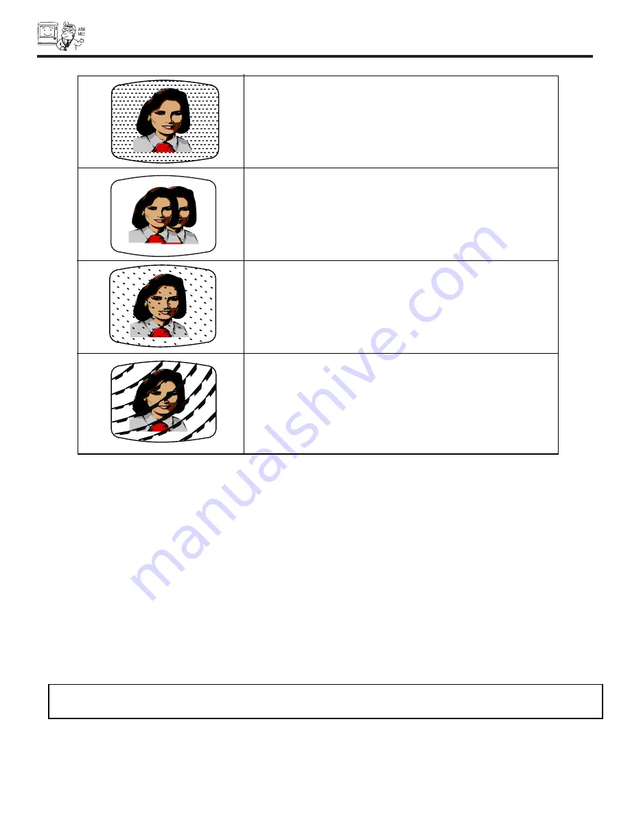
• IGNITION NOISE:
Black spots or horizontal streaks may appear, picture may flutter or drift.
Usually caused by interference from automobile ignition systems, neon
lamps, electrical drills, and other electrical appliances.

• GHOSTS:
Ghosts are caused by the television signal following two paths.  One is the
direct path and the other is reflected from tall buildings, hills or some other
objects.  Changing the direction or position of the antenna may improve
reception. Ghosting may also be caused by defects in the antenna system
such as unshielded leads or connecting several sets to the same antenna
without using multiple antenna couplers.

• SNOW:
If your receiver is located in the fringe area of a television station where
the signal is weak, your picture may be marred by the appearance of small
dots.  When the signal is extremely weak, it may be necessary to install a
special antenna to improve the picture.

• RADIO FREQUENCY INTERFERENCE:
The interference produces moving ripples or diagonal streaks, and in
some cases, causes loss of contrast in the picture.

NOTE:

The TV set can generate sound distortion in external devices such as a radio.  Please separate radio equipment 
from the TV set to a considerable distance.

Summary of Contents for 50V500 - UltraVision Digital - 50" Rear Projection TV

Page 1: ...NS 2 3 FIRST TIME USE 4 22 THE REMOTE CONTROL ON SCREEN DISPLAY USEFUL INFORMATION INDEX 69 80 44 68 23 43 Locks Chan Manager Aspect Audio Video Move SEL Sel Setup As an ENERGY STAR Partner Hitachi Ltd has determined that this product meets the ENERGY STAR guidelines for energy efficiency ...

Page 2: ... the appliance NOTE There are no user serviceable parts inside the television Model and serial numbers are indicated on back side of the television POWER SOURCE THIS TELEVISION IS DESIGNED TO OPERATE ON 120 VOLTS 60Hz AC CURRENT INSERT THE POWER CORD INTO A 120 VOLT 60Hz OUTLET TO PREVENT ELECTRIC SHOCK DO NOT USE THE TELEVISION S POLARIZED PLUG WITH AN EXTENSION CORD RECEPTACLE OR OTHER OUTLET UN...

Page 3: ...low instructions for wall shelf or ceiling mounting as rec ommended by the manufacturer 17 An outdoor antenna should not be located in the vicinity of overhead power lines or other electrical circuits 18 If an outside antenna is connected to the receiver be sure the antenna system is grounded so as to provide some protec tion against voltage surges and built up static charges Section 810 of the Na...

Page 4: ... type Check to make sure you have the following accessories before disposing of the packing material 3 2 POWER TV VCR CBL DVD 1 2 4 5 6 3 7 8 9 0 INFO SLEEP A V NET EX IT MEN U CH VOL MUTE PIP SURF SWAP FREEZE PIP MODE PIP ACCESS DAY NIGHT SOURCE WIZARD REC SELECT C C ASPECT STB ANT LAST CH VID1 VID2 VID3 VID4 VID5 PVR CD AMP VIDEO CLU 5729TSI REMOTE CONTROL BATTERIES AA IR MOUSE CABLE 1 FIRST TIM...

Page 5: ...st audio performance will be obtained by placing the speakers equidistant from each side of the receiver cabinet and as close as possible to the height of the picture screen center For best stereo separation place the external speakers at least four feet from the side of the TV place the surround speakers to the side or behind the viewing area Differences in room sizes and acoustical environments ...

Page 6: ...can be purchased from most stores that sell audio video products Below are illustrations and names of common connectors Before purchasing any cables be sure of the output and input connector types required by the various components and the length of each cable 300 Ohm Twin Lead Connector This outdoor antenna cable must be connected to an antenna adapter 300 Ohm to 75 Ohm Phono Connector Used on al...

Page 7: ... when in MENU mode When the TV power is turned OFF at a volume level 31 or greater the volume level will default to 30 when the TV is turned ON However if it is set to a level 30 or less the volume level will be at the level it was set when the TV is turned ON FRONT INPUT JACKS INPUT 5 Use these audio video jacks for a quick hook up from a camcorder or VCR to instantly view your favorite show or n...

Page 8: ...BLINKING LIGHT ON SLOWLY BLINKING INDICATOR INDICATION MEANING ACTION LAMP LED TEMP LED POWER Need to replace if LAMP still does not light by Power On again Check assembly condition of LAMP UNIT Call for Service NOTES 1 2 If the LAMP TEMP and POWER LED are blinking in the order below the television is warming up POWER TEMP LAMP FIRST TIME USE IMPORTANT NOTES 1 A small number of missing discolored ...

Page 9: ...letely insert connection cord plugs when connecting to front panel jacks If you do not the played back picture may be abnormal 2 If you have a S VHS VCR use the S INPUT cable in place of the standard video cable 3 If you have a mono VCR insert the audio cable into the left audio jack of your TV INPUT 5 S VIDEO VIDEO AUDIO L MONO R INPUT 5 S VIDEO VIDEO AUDIO L MONO R FIRST TIME USE ...

Page 10: ...uality video output AUDIO TO HI FI Output These jacks provide variable audio output to a separate stereo amplifier With this connection the audio to the stereo can be controlled by the television s main volume CENTER IN Input This jack is for stereo amplifiers with center signal capability This feature allows the TV speakers to be used as a center speaker The TV must be set as a center channel by ...

Page 11: ...ght infringement the MONITOR OUT output will be abnormal when using the Y PBPR jacks 6 Input 2 Y VIDEO can be used for composite video and component video input IR Blaster This jack provides IR output to your external components VCR Cable box DVD player etc With this connection your external components can automatically be controlled by the AV Net feature This connection will allow you to control ...

Page 12: ...Laserdisc player VCR camcorder etc HDTV Set Top Box DVD Player Cable TV Box VCR 1 ANT IN OUTPUT S VIDEO V L R Provided Provided D VHS DIGITAL OUTPUT L R OUTPUT OUTPUT Y PB CB PR CR L R VCR 2 V L R OUTPUT S VIDEO V L R INPUT S VIDEO OUTPUT Y PB PR L R CONNECT TO IR BLASTER CONNECT TO IR BLASTER IR Sensor IR Sensor PB PR CENTER IN PB PR DVI HDTV CENTER OUTPUT L R INPUT OUTPUT INPUT ANT A TO CONVERTE...

Page 13: ...nt VCR DVD player camcorder etc to each input jack COMPONENT Y PBPR Input 1 2 connections are provided for high performance components such as DVD players and set top boxes Use these connections in place of the standard video connection if your device has this feature Input 2 accepts both composite and component video signals Your component outputs may be labeled Y B Y and R Y In this case connect...

Page 14: ...adjust the sound using the remote control of the TV set 2 Follow connections that pertain to your personal entertainment system 3 See page 50 for Audio Settings REAR PANEL OF TELEVISION PB PR CENTER IN PB PR DVI HDTV L R INPUT ANT A TO CONVERTER ANT B Y R MONO L IR BLASTER AUDIO TO HI FI S VIDEO S VIDEO S VIDEO Y VIDEO R MONO L R MONO L VIDEO R MONO L VIDEO R L VIDEO INPUT 1 INPUT 2 INPUT 3 INPUT ...

Page 15: ...t the VCR camcorder laserdisc player DVD player or HDTV Set Top Box to your TV set is dependent on the model and features of each component Check the owner s manual of each component for the location of video and audio inputs and outputs The following connection diagrams are offered as suggestions However you may need to modify them to accommodate your partic ular assortment of components and feat...

Page 16: ...ter approximately four seconds 5 Press the ANT button to return to the previous channel NOTES 1 Completely insert the connection cord plugs when connecting to rear panel jacks The picture and sound that is played back will be abnormal if the connection is loose 2 A single VCR can be used for VCR 1 and VCR 2 see page 12 but note that a VCR cannot record its own video or line output Refer to your VC...

Page 17: ...ter approximately four seconds 5 Press the ANT button to return to the previous channel NOTES 1 Completely insert the connection cord plugs when connecting to rear panel jacks The picture and sound that is played back will be abnormal if the connection is loose 2 A single VCR can be used for VCR 1 and VCR 2 see page 12 but note that a VCR cannot record its own video or line output Refer to your VC...

Page 18: ... L IR BLASTER AUDIO TO HI FI R S VIDEO S VIDEO S VIDEO Y VIDEO R MONO L R MONO L VIDEO R R L VIDEO INPUT 2 INPUT 3 MONITOR OUT AUDIO AUDIO AUDIO L R OUTPUT DIGITAL OUTPUT DIGITAL OUTPUT CAPABILITY INPUT 1 MONO L VIDEO INPUT 4 NOTES 1 Completely insert the connection cord plugs when connecting to rear panel jacks The picture and sound that is played back will be abnormal if the connection is loose ...

Page 19: ...of the Laserdisc DVD player or HDTV set top box to the INPUT AUDIO L jack 6 Press the VID1 or VID2 button to view the program from the Laserdisc DVD player or HDTV set top box The VIDEO OSD label disappears automatically after approximately four seconds 7 Press the ANT button to return to the previous channel NOTES 1 Completely insert the connection cord plugs when connecting to rear panel jacks T...

Page 20: ... s rear panel 3 Place the IR mouse in front of the infrared sensor of the external components you wish to control NOTES 1 The rear panel has two IR BLASTER inputs which can control up to a total of four external components 2 The IR Mouse must be placed in front of the external components IR sensor for the AV Network to work 3 The correct codes must be entered for each of the Audio Video components...

Page 21: ...NG LIST Device Code Video Audio DVD 0672 INPUT 1 Using TV VCR Not Setup Not Setup CBL Not Setup Not Setup STB Not Setup Not Setup PVR Not Setup Not Setup AVR Not Setup Not Setup Custom Not Setup Not Setup EXIT HITACHI AV NET SET UP DVD Device Code 0 6 7 2 Enter code 9999 to uninstall Video Input Input 1 Audio Input Using TV Transmission Test POWER PLAY CH UP BACK OK EXIT Move SEL Select Set Input ...

Page 22: ...amaha 0490 0545 0539 Zenith 0591 0503 CABLE BRAND CODE ABC 0003 0008 0014 0017 Americast 0899 Bell Howel 0014 Bell South 0899 Director 0476 General Instrument 0003 0476 0276 0810 GoldStar 0144 Hamlin 0009 0273 Jerrold 0476 0003 0276 0012 0014 0810 Memorex 0000 Motorola 0476 1106 0276 0810 Pace 0237 Panasonic 0107 0000 Philips 0305 0317 Pioneer 0144 0533 0877 1877 Pulsar 0000 Quasar 0000 Regal 0273...

Page 23: ...ons on how to program the remote to control your set top box To operate your DVD player point the remote at the remote sensor of the DVD player and press the DVD button The DVD but ton will blink indicating that the remote will now control your DVD player see page 40 for instruction on how to program the remote to control your DVD player To operate your PVR Personal Video Recorder point the remote...

Page 24: ...sed it will blink to indicate the remote is in CABLE mode see page 38 SET TOP BOX STB When the STB button is pressed it will blink to indicate the remote is in STB mode see page 39 If you have a Satellite receiver use this button to program your Satellite receiver see page 39 DVD button When the DVD button is pressed it will blink to indicate the remote is in DVD mode see page 40 24 25 POWER TV VC...

Page 25: ...er in the lower left corner of the screen Every subsequent press of this button will add 15 minutes to this timer up to a maximum of three hours Once set use INFO when you want to view time remaining If the SLEEP button is pressed while the timer is set it will reset to the original condition The DASH button can only be used when the remote control is in Set Top Box STB mode INFO button Press this...

Page 26: ...equipment soft keys The equipment list will scroll up or down Photo MC Cable Box DVD Move POWER MENU MORE THUMB STICK SELECT THUMB STICK INFO Device Setting Photo MC Cable Box DVD Move POWER MENU MORE SEL Previous Page 1 2 3 4 5 6 7 0 9 8 MORE Move POWER INFO Device Setting CH CH MENU TV VCR MORE Move POWER SEL Previous Page CH CH MENU TV VCR MORE 1 2 3 4 5 6 7 0 9 8 THUMB STICK SELECT MORE THUMB ...

Page 27: ...0 6 10 5 10 9 10 10 10 THUMB STICK 1 10 2 10 3 10 4 10 8 10 7 10 6 10 5 10 9 10 10 10 No 7 10 03 04 03 1632x1232 Picture No Date Resolution 1 10 2 10 3 10 4 10 8 10 7 10 6 10 5 10 9 10 10 10 1 10 2 10 3 10 4 10 8 10 7 10 6 10 5 10 9 10 10 10 Jump Slideshow Rotate Please Enter Picture Number 1 10 2 10 3 10 4 10 8 10 7 10 6 10 5 10 9 10 10 10 No 7 10 03 04 03 1632x1232 Picture No Date Resolution THU...

Page 28: ... time from 5 10 and 30 seconds Each press will change interval time from the three mentioned choices Press SELECT to stop on a chosen picture of the slideshow After 30 seconds the slideshow will resume or press SELECT again to continue the slideshow Press EXIT to exit the slideshow NOTES 1 Photo file names modified on a computer should be 8 characters Ex ABCD1234 jpg 1st character letters 2nd to 4...

Page 29: ... CH CH MENU TV VCR INFO GUIDE MORE THUMB STICK Custom Set Top Box Move INFO Device Setting Custom Set Top Box Move INFO Device Setting THUMB STICK SETUP THUMB STICK POWER CH CH MENU INFO GUIDE 1 2 3 4 5 6 7 0 9 8 LAST CH Photo MC Cable Box DVD Move POWER MENU MORE INFO Device Setting THUMB STICK C See Page 30 B HITACHI AV NET WIZARD Learning Use this wizard to manually learn or modify your AV NET ...

Page 30: ...ning Transfer was successfull Press OK to continue BACK OK OK HITACHI AV NET WIZARD Learning Select another DVD2 softkey to learn TV Softkeys Done Continue POWER MENU SELECT EXIT Done HITACHI AV NET WIZARD Learning DVD2 Custom Video Input No Connection Audio Input No Connection Transmission Test POWER PLAY CH UP BACK OK EXIT OK HITACHI AV NET SETTING LIST Device Code Video Audio DVD 0672 INPUT 1 U...

Page 31: ... to fill it 4 3 Zoom1 Zoom2 Use these aspect modes to zoom in on conventional 4 3 sources 16 9 Standard Use this aspect mode to display 16 9 sources like HDTV and DVD s preserving the original 16 9 aspect ratio 16 9 Zoom Use this aspect mode to zoom 16 9 images 1 NTSC 480i 480p Input 2 480i 480p INPUT 3 720p 1080i INPUT 4 3 INPUT 4 3 EXPANDED 4 3 ZOOM1 4 3 ZOOM2 16 9 STANDARD 4 3 STANDARD INPUT 4 ...

Page 32: ...l the channel from the Favorite Channel use THUMB STICK to highlight the channel then THUMB STICK to highlight Delete Del and press SELECT to delete To view a Favorite Channel use THUMB STICK to highlight the channel and press SELECT to view Favorite Channels Move Ant A 8 A 6 A 3 THUMB STICK THUMB STICK Add SEL Tune Favorite Channels Move Ant A 8 A 8 A 6 A 3 Del 8 THUMB STICK SELECT VOLUME MUTE bu...

Page 33: ...th more brightness and contrast to compete with room light Select Night for night time viewing with less brightness and contrast for a more detailed picture see page 46 for settings changes 1 23 24 3 32 PM Ant A 10 Stereo R 3 32 PM Ant A 39 Stereo R LAST CH Ant A 28 TAKA YPBPR 1 VID1 Stereo ST SA Video 2 VID2 Video 4 VID4 Video 5 VID5 Video 3 VID3 VID 1 VID 2 VID 3 VID 4 VID 5 Ant SURF SURF NOTES ...

Page 34: ...nd DVI HDTV To prevent a pattern burn occasionally move the sub picture using the THUMBSTICK NOTES 1 In POP mode THUMBSTICK will move the sub picture up down 2 Only sound from the main picture can be heard Main Picture Sub Picture PIP Your HITACHI LCD Rear PTV incorporates dual tuner technology designed for improved viewing enjoyment This dual tuner feature allows you to view antenna inputs on bot...

Page 35: ...B 480i 480p 720p 1080i PICTURE IN PICTURE PIP MODES PIP MODE 4 PIP MODE PIP MODE PIP MODE Freeze Freeze Freeze PIP MODE Freeze Freeze Freeze NOTE PIP modes will depend on the type of signal format received PIP MODE button To change between the available PIP modes moving picture SPLIT POP or PIP freeze picture SPLIT STROBE MAIN and SUB press the PIP MODE button when PIP is ON Each press of this but...

Page 36: ...nd 2 When in Ant A Ant B the FREEZE mode cycles through POP main POP sub SPLIT and STROBE NOTE When PIP is on the FREEZE function will only operate when POP PIP SPLIT mode is chosen Hot Springs Clay Mask C O John Doe Run Spa Retreat P O Box 55512 Any Town USA 98765 Check or Money Order Only 1 800 555 1212 STROBE FREEZE with PIP OFF PIP should be in SURF mode Press the FREEZE button to freeze three...

Page 37: ...mote 2 In the unlikely event that your VCR cannot be operated after performing the above procedures please consult your VCR operating guide 3 The remote control will remember the codes you have programmed until the batteries are removed from the remote control After replacing the batteries repeat the entire programming procedure as stated above 4 The MENU button will act as the VCR MENU button for...

Page 38: ...le box code has not been precoded into the remote 2 In the unlikely event that your cable box cannot be operated after performing the above procedures please consult your cable box operating guide 3 The remote control will remember the codes you have programmed until the batteries are removed from the remote control After replacing the batteries repeat the entire programming procedure as stated ab...

Page 39: ... receiver NOTES 1 If your set top box satellite receiver cannot be operated after performing the above procedures your set top box satellite receiver code has not been precoded into the remote 2 In the unlikely event that your set top box satellite receiver cannot be operated after performing the above procedures please consult your set top box satellite receiver operating guide 3 The remote contr...

Page 40: ...set the display type of your DVD player to 16 9 widescreen NOTES 1 If your DVD player cannot be operated after performing the above procedures your DVD player s code has not been precoded into the remote 2 In the unlikely event that your DVD player cannot be operated after performing the above procedures please consult your DVD player operating guide 3 The remote control will remember the codes yo...

Page 41: ... NOTES 1 If your PVR cannot be operated after performing the above procedures your PVR s code has not been precoded into the remote 2 In the unlikely event that your PVR cannot be operated after performing the above procedures please consult your PVR operating guide 3 The remote control will remember the codes you have programmed until the batteries are removed from the remote control After replac...

Page 42: ...ponent Be sure to use a different Audio button on the remote since only one component can be programmed per button NOTES 1 If your Audio component cannot be operated after performing the above procedures your Audio component s code has not been precoded into the remote 2 In the unlikely event that your Audio component cannot be operated after performing the above procedures please consult your Aud...

Page 43: ...g 12 Sanyo 13 Sony 02 Toshiba 05 Yamaha 08 Zenith 05 11 CABLE BRAND CODE ABC 01 07 08 17 18 20 36 37 49 Antronix 39 Archer 11 24 39 Belcor 32 Cable Star 32 Century 11 Citizen 11 Colour Voice 30 42 Comtronics 25 28 Contec 21 Dae Ryung 20 Eastern 14 Electricord 31 Everquest 51 Focus 52 Garrard 11 GC Electronics 32 39 Gemini 05 38 43 51 General Instrument 01 12 Goldstar 10 25 Hamlin 04 13 22 23 Hitac...

Page 44: ...trol to quickly exit from a menu 4 Press A V Net on the remote control to access the AV Net menu to control external components 5 Press THUMB STICK or to access Favorite Channels menu EXIT MENU SELECT A V Net Locks Chan Manager Aspect Audio Video Move SEL Sel Setup This part of the screen shows which selections are available This part of the screen shows which Remote Control buttons to use ON SCRE...

Page 45: ...ect TV s internal speakers On Off or use as center speaker Auto Noise Cancel Eliminates the noise from inactive stations Perfect Volume Adjust volume for a fixed setting Loudness Adjust Loudness Mode Choose the picture format aspect ratio Ant A View edit Channel ID Scan and Lock settings in antenna A Ant B View edit Channel ID Scan and Lock settings in antenna B Change Access Code Change Lock acce...

Page 46: ...CT THUMB STICK Color Brightness Contrast Picture Mode Video Move SEL Select Color Temperature Sharpness Tint Contrast Mode Black Enhancement 100 50 50 50 High Locks Chan Manager Aspect Audio Video Move SEL Sel SEL Select Day Night Setup Reset Video Settings ANT A B High Dynamic Picture Mode Day Night Return Next Prev Contrast 100 90 Brightness 50 50 Color 50 30 Tint Center Center Sharpness 50 30 C...

Page 47: ... in the same manner 2 It may be necessary to adjust TINT to obtain optimum picture quality when using the COMPONENT VIDEO Y PBPR input jacks Use this function to adjust flesh tones so they appear natural Tint Use this function to adjust the amount of fine detail in the picture Sharpness function will be disabled when Noise Reduction is On Sharpness Use this function to choose between 3 Contrast Mo...

Page 48: ... g s o n t h i s i n p u t t o t h e o r i g i n a l f a c t o r y s e t t i n g s R e s e t THUMB STICK SELECT THUMB STICK Color Brightness Contrast Picture Mode Video Move SEL Select Color Temperature Sharpness Tint Contrast Mode Black Enhancement 100 50 50 50 High Day Night Reset Video Settings ANT A B High Dynamic Noise Reduction Auto Color Color Decoding Video Move SEL Select Auto Movie Mode ...

Page 49: ... Theatrical movies are shot on film at 24 frames or still pictures per second instead of 30 frames or 60 fields like video When film is transferred to video for television viewing the disparity between the two frame rates must be reconciled This involves a process known as 3 2 pulldown When Auto Movie Mode is turned On from the Video menu your Hitachi LCD TV will activate the circuitry for this sp...

Page 50: ...econdary language weather report etc The sources received will be displayed at the top right edge of the TV The source you select will be displayed above the sources received See example below for each selection when both stereo and second audio are received monaural is always received This function is useful when setting up the external speakers ON Select this feature if using the internal speake...

Page 51: ...nnel speakers of your HITACHI LCD television If your HITACHI LCD television is connected to an external audio system BBE will also create an incredible crisp sound experience from two speakers and even more complete and accurate repro duction of the original performance BBE brings to the listener s ear a more complete and accurate reproduction of the original per formance Each voice speaking or si...

Page 52: ...p and bottom of the picture with 480i 480P signal Adjustable range is 10 video center is toward bottom of screen to 10 video center is toward top of screen Press THUMB STICK to select menu item Press THUMB STICK or to adjust the function Press EXIT to quit the MENU or select Aspect to return to the main menu Use this function to select the Picture Format Aspect Ratio NOTES 1 The Auto Aspect functi...

Page 53: ...rn Channel Source Antenna Cable 1 Cable 2 Auto Channel Scan Start THUMB STICK SELECT THUMB STICK Move SEL Select Channel Source Antenna Cable 1 Cable 2 Auto Channel Scan Start Ant B Chan Manager Move SEL Select Ant A Channel List Chan Manager Ant A Channel List Chan Manager Ant A RECEPTION BAND CATV 1 OR CATV 2 AIR VHF 2 13ch UHF 14 69ch CATV CHANNEL VHF 2 13 Mid band A 1 A 5 A 1 Super band J W Hy...

Page 54: ...an for the second antenna input Remember to select the correct Antenna Cable mode before using Auto Channel Scan See Channel Manager Scan to add or to erase additional channels Auto Channel Scan THUMB STICK SELECT THUMB STICK SEL Cancel Cancel Scanning Channel Number 66 Move SEL Select Channel Source Auto Channel Scan Start Chan Manager Ant A Channel List Antenna Cable 1 Cable 2 Move SEL Select Ch...

Page 55: ...nnel or buttons Scan To add Scan On or skip Scan Off additional channels while in Channel Manager THUMB STICK to highlight the channel number then THUMB STICK or to highlight other channels Once the desired channel is highlighted THUMB STICK to scan column then THUMB STICK or to select ON or OFF THUMB STICK Move SEL Return Ch Scan CH ID Lock 2 Off 3 Off 4 Off 5 Off 6 Off 7 Off 8 Off 9 Off Move SEL...

Page 56: ...e mode the Channel ID for both antenna inputs will be the same 2 Channel ID will not be displayed when PIP is ON Channel ID Move Edit A Z 0 9 _ Ch Scan Ch ID Lock 2 On 3 On 4 Off 5 Off 6 Off 7 Off 8 Off 9 Off SEL Return Ch Scan Ch ID Lock 2 On A 3 On 4 Off 5 Off 6 Off 7 Off 8 Off 9 Off Ch Scan Ch ID Lock 2 On A 3 On 4 Off 5 Off 6 Off 7 Off 8 Off 9 Off THUMB STICK THUMB STICK THUMB STICK Move Edit ...

Page 57: ...nt Panel Lock can be set individually When Set Channel Lock is turned on the picture and sound for the chosen channel will be blocked out When Set Input Lock is turned on the picture and sound for all video inputs and the picture and sound for channels 3 4 of Ant A B will be blocked out When Front Panel Lock is turned on all buttons on the Front Panel will be deactivated except the Power button Wh...

Page 58: ...d G PG PG 13 R NC 17 X MENU THUMB STICK Movie Ratings TV Time Lock Engage Lock Change Access Code Locks Move SEL Select Canadian Ratings Frn Canadian Ratings Eng TV Ratings Movie Ratings Locks Contains no rating Not Rated NR and Not Applicable NA pro grams Movie has not been rated or ratings do not apply Restricted Under 17 requires accompanying parent or adult guardian Parents strongly cautioned ...

Page 59: ...include mild physi cal or comedic violence or may frighten chil dren under the age of 7 All children The themes and elements in this program are specifically designed for a very young audience including children from ages 2 6 General audience It contains little or no vio lence no strong language and little or no sex ual dialogue or situations TV Y TV Y7 TV G TV PG TV 14 TV MA Parents strongly caut...

Page 60: ...ence will be infrequent discreet of low intensity and will show the consequences of the acts Other Content Guidelines There will be no profanity nudity or sexual content General Audience Violence Guidelines Will contain very little violence either physi cal or verbal or emotional Will be sensitive to themes which could frighten a younger child will not depict realistic scenes of violence which min...

Page 61: ...8 General Not recommended for young children Programming intended for a broad audience but contains light or occasional violence that could disturb young children Viewing with an adult is therefore recommended for young children under the age of 8 who can not differentiate between real and imaginary portrayals General Programming intended for audiences of all ages Contains no violence or the vio l...

Page 62: ...spañol Set The Menu Background Shaded Solid MENU Move SEL Select Set The Language English Français Español Set The Menu Background Shaded Solid THUMB STICK Menu Preference Setup Menu Preference Setup THUMB STICK SELECT Set The Inputs Set The Clock Screen Saver Menu Preference Setup Move SEL Select Set Event Timer Set Black Side Panel Set The Color System Set Closed Captions Setup MENU THUMB STICK ...

Page 63: ... Use the SCREEN SAVER feature to avoid remain picture Moving picture will clear up the remain picture Use THUMB STICK to highlight Screen Saver s Main Picture Moving options Press down on THUMB STICK to select and EXIT to quit Option 1 The whole picture will shift every 20 minutes by two pixels Option 2 The whole picture will shift every 40 minutes by two pixels Option 3 The whole picture will shi...

Page 64: ...STICK Time 03 57 PM Apr 29 2003 Move SEL Return Time 03 57 PM Apr 29 2003 THUMB STICK Set Setup Set The Clock Setup Set The Clock Setup Set The Clock Set The Inputs Set The Clock Screen Saver Menu Preference Setup Move SEL Select Set Event Timer Set Black Side Panel Set The Color System Set Closed Captions Use THUMB STICK or to set the time and date Press THUMB STICK or to change position Press EX...

Page 65: ...TV will turn on and switch to Video2 automatically when the Video2 input device is turned on and the VCR laserdisc or DVD play button on your remote control is pressed This is convenient when you want to record a movie with your VCR and watch it later Select Off to disable this function Press EXIT to quit menu Video 2 Auto Link NOTES 1 Once the TV has been turned on using the Auto Link feature it ...

Page 66: ...h actual input signal the color and tint of the main picture will be abnormal 2 You must be tuned to VIDEO 1 or 2 inputs and have a component hooked up to the Y PBPR input jacks to access this color system 3 All component color type settings will affect only color component input you are currently viewing If you are using both sets of component input jacks be sure to set the color system feature f...

Page 67: ... SEL On Off Event 1 AM AM Ant A Ch Once Event 2 AM AM Ant A Ch Once Event 3 AM AM Ant A Ch Once THUMB STICK Return Setup Set Event Timer Setup Set Event Timer Set The Inputs Set The Clock Screen Saver Menu Preference Setup Move SEL Select Set Event Timer Set Black Side Panel Set The Color System Set Closed Captions Please Set Clock First If the clock is not set you can not use this function and th...

Page 68: ...y on or off Auto will turn the display on when Mute Soft Mute is on Caption Mode Captions is for the program you are viewing Text is for additional information such as news reports or a TV program guide This information covers the entire screen and viewing the TV program is not possible Text may not be available with every program CHANNEL 1 is used for the primary language usually English 2 is som...

Page 69: ...g in the U S or Electronic Product Stewardship Canada at www epsc ca in Canada CAUTION A LAMP indicator will light when lamp becomes hot Unplug product s power cord from the AC outlet and allow lamp to cool for at least 30 45 minutes If LAMP indicator is still lit please contact your authorized service center see page 77 78 NOTES Contact your Hitachi dealer for a new lamp unit Using other lamps ma...

Page 70: ...EEDING WITH LAMP REMOVAL FRONT COVER PUSH PULL LAMP COMPARTMENT 2 Remove the front cover from the TV set This is held by a snap on Pull the front cover outwards until the quick snap on disengages NOTE The lamp in this product contains Mercury Dispose of properly in accordance with applicable environmental laws For Recycling and Disposal information contact your respective governmental agencies or ...

Page 71: ...MP STORAGE AREA AFTER THE LAMP UNIT IS REMOVED YOU MAY GET BURNED 5 Replace with the new lamp Place the removed lamp into the empty box of the replacement lamp Do not touch the front glass of the new lamp or its receptacle This may shorten the life of the lamp and reduce the picture quality Push the lamp unit back to its original position Tighten the screws firmly on the lamp unit If they are loos...

Page 72: ... as shown below Put the front cover back in and align the snap on quick connect then push inwards hold ing the left and right side of the front cover until you hear a snap Push the other snap on gently to make a good fit FRONT COVER PUSH PUSH 8 Plug power cord into AC outlet and turn on the main power switch 120V PUSH POWER LAMP REPLACEMENT NOTE The lamp in this product contains Mercury Dispose of...

Page 73: ...ouch the screen too often Do not subject the remote control to shocks such as dropping it on the floor etc Physical damage to the precision parts may result Avoid placing the remote control in a high humidity place or getting it wet Do not leave it on or near a heater Excessive heat or moisture may cause the unit to cease operation When the batteries run down remote control operation will become e...

Page 74: ...efects in the antenna system such as unshielded leads or connecting several sets to the same antenna without using multiple antenna couplers SNOW If your receiver is located in the fringe area of a television station where the signal is weak your picture may be marred by the appearance of small dots When the signal is extremely weak it may be necessary to install a special antenna to improve the p...

Page 75: ...C H E C K T H E S E I T E M S A N D T R Y T H E S E A D J U S T M E N T S No Picture no sound Sound OK picture poor Picture OK sound poor Picture blurred Lines or streaks in picture Poor reception on some channels Picture rolls vertically No color Poor color B e s u r e e x t e r n a l c o n n e c t i o n i s c o r r e c t B e s u r e p o w e r c o r d i s p l u g g e d i n B e s u r e T V i s s w...

Page 76: ...Control up to 4 components with one remote 2 IR Mouse cables included Full Set of Input Jacks including S VIDEO COMPONENT VIDEO Y PB PR Inputs Power Input AC 120V 60Hz Stand by Power 0 6W Power Consumption Refer to rear panel at the back of the T V Antenna input impedance 75 Ohm Channel coverage 181ch VHF Band 2 13 UHF Band 14 69 CATV Mid Band A 5 A 1 A I Super Band J W Hyper Band W 1 W 28 Ultra B...

Page 77: ...Hitachi Authorized Service Facility nearest you Just present proof of purchase and or delivery receipts to the Hitachi Authorized Service Facility and serv ice will be rendered in accordance with the terms of the limited warranty as stated on your warranty card or operating guide Should you have any questions regarding warranty service operation or technical assistance please contact To locate an ...

Page 78: ...g call for a copy 1 800 HITACHI 1 800 448 2244 Au Canada 1 800 HITACHI 1 800 448 2244 Lundi Vendredi L EST 9 00am 7 00pm Samedi L EST 9 00am 5 00pm Pour de plus amples renseignements sur le service durant la période couverte par la garantie sur le fonction nement ou pour de l assistance technique communiquez avec La version français de votre manual se trouve a l exterieur de la boîte Si le manuel ...

Page 79: ...ntrast 47 BBE 51 Audio Settings 50 51 D Audio Source 50 DVI HDTV 11 12 18 Audio Video Network A V Net 21 22 26 29 30 Auto Color 49 Auto Noise Cancel 50 E Event Timer AV Net ANT A B 67 AV Net Code 22 AV Net Setup 20 21 AV Net Usage 26 30 B Balance 50 Bass 50 Black Enhancement 47 I Black Side Panel 66 Input Setup 65 Brightness 47 IR Blaster 11 20 C Channel Manager 53 54 Channel Setup 54 Auto Channel...

Page 80: ...e Lock 57 Movie Ratings 58 TV Ratings 59 S TV Ratings Canadian English 60 TV Ratings Canadian French 61 Sharpness 47 Loudness 50 Sound Enhancement 51 Speakers 50 M Connecting External Speakers 5 12 13 Menu Preference Language 62 T Background 63 Temperature Indicator 8 Monitor Out 10 Time 62 Tint 47 Treble 50 V Vertical Position 52 N Video Settings 46 49 Virtual HD 66 Noise Reduction 49 P Power But...

Page 81: ...81 NOTES ...

Page 82: ...82 NOTES ...

Page 83: ...NOTES 83 ...

Page 84: ...QR57022 ...

Reviews: