52
PT5-G/PW1-H
Self Diagnosis Function
˙
PDP Monitor [42HDT51,55HDT51]
Sub-Power button also activates Self Diagnosis mode for a PDP monitor failure with no picture.
To enter to Self Diagnosis mode, follow the next conditions and steps:
Conditions:
1) The connection cable between the Monitor and AVC (DVI and DIN) must be unplugged from the Monitor.
2) Make sure Power Cord of AC line is connected to the PDP Monitor.
3) The Main Power switch must be turned on.
Procedure:
42": 1) Press Sub-Power button for more than 5 seconds.
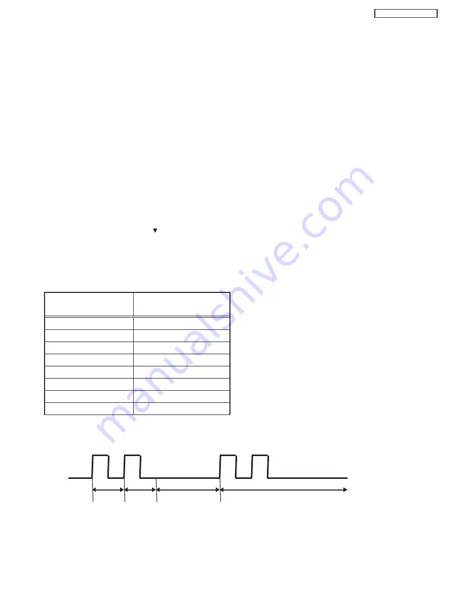
2) It generates red blinking series of the power indicator light when PDP Monitor has some failure.
3) If PDP Monitor has no failure, it enters Burn-in mode.
4) Turning off the Main Power switch would cancel the Self Diagnosis mode.
5) The next table shows the PDP PWB in which failure most probably would be allocated according
to the number of blinks.
55": 1) Press Sub-Power button and
button on the bottom of the monitor at the same time, and keep it for
more than 5 seconds after the power turned on.
2)It generates red blinking series of the power indicator light.
3)Any operation would cancel the Self-Diagnosis mode.
4)The next table shows the PDP PWB in which failure most probably would be allocated according
to the number of blinks.
Number of red blinks
Presumed failing PWB
of power indication light
1
Logic
2
X-SUS
3
Y-SUS
4
X-SUS, Y-SUS, SDM, PSU
SDM: Scan Driver Module
5
ADM, PSU, ABUS
PSU: Power Supply Unit
6
ADM
ADM: Address Driver Module
7
ADM
8
All PWBís
Note) SDM is permanently contacted to glass part.
[Blinking condition of power indication light]
ex. 2 blinks
1 sec
1 sec
2 sec OFF
Repeat
a
b
a
b
11. PDP TROUBLESHOOTING FLOWCHARTS
Summary of Contents for 42HDT51M
Page 12: ...12 PT5 G PW1 H TABLE OF CONTENTS Specification Features A Plasma ...
Page 13: ...13 PT5 G PW1 H ...
Page 14: ...14 PT5 G PW1 H B Environment ...
Page 15: ...15 PT5 G PW1 H ...
Page 16: ...16 PT5 G PW1 H ...
Page 30: ...30 PT5 G PW1 H 5 7 WHITE BALANCE ADJUSTMENT OSD FLOW DIAGRAM BACK TO ADJUSTMENTS ...
Page 32: ...32 PT5 G PW1 H 9 SETTING for Delivery ...
Page 33: ...33 PT5 G PW1 H 9 SETTING for Delivery continued ...
Page 34: ...34 PT5 G PW1 H 9 SETTING for Delivery continued ...
Page 35: ...35 PT5 G PW1 H 9 SETTING for Delivery continued ...
Page 36: ...36 PT5 G PW1 H 9 SETTING for Delivery continued ...
Page 53: ...53 PT5 G PW1 H 12 Circuit Block Diagram MONITOR ...
Page 54: ...54 PT5 G PW1 H MONITOR ...
Page 55: ...55 PT5 G PW1 H 12 Power Circuit Block Diagram MONITOR ...
Page 56: ...56 PT5 G PW1 H MONITOR ...
Page 57: ...57 PT5 G PW1 H 12 2 MPU Control Block Diagram MONITOR ...
Page 58: ...58 PT5 G PW1 H MONITOR ...
Page 64: ...FINAL WIRING DIAGRAM MONITOR 64 PT5 G PW1 H ...
Page 65: ...FINAL WIRING DIAGRAM MONITOR 65 PT5 G PW1 H ...
Page 66: ...FINAL WIRING DIAGRAM MONITOR 66 PT5 G PW1 H ...
Page 67: ...FINAL WIRING DIAGRAM MONITOR 67 PT5 G PW1 H ...
Page 95: ...AVC5U 95 PRINTED CIRCUIT BOARDS AV P W B CS TABLE OF CONTENTS ...
Page 96: ...96 AVC5U PRINTED CIRCUIT BOARDS AV P W B SS TABLE OF CONTENTS ...
Page 97: ...97 AVC5U PRINTED CIRCUIT BOARDS CONTROL P W B TABLE OF CONTENTS ...
Page 98: ...98 AVC5U PRINTED CIRCUIT BOARDS HDMI P W B CS TABLE OF CONTENTS ...
Page 99: ...99 AVC5U PRINTED CIRCUIT BOARDS HDMI P W B SS TABLE OF CONTENTS ...
Page 100: ...100 AVC5U PRINTED CIRCUIT BOARDS SW P W B SS TABLE OF CONTENTS ...
Page 101: ...101 PT5 G PRINTED CIRCUIT BOARDS FILTER P W B CS TABLE OF CONTENTS ...
Page 102: ...102 PT5 G PRINTED CIRCUIT BOARDS FILTER P W B SS TABLE OF CONTENTS ...
Page 103: ...103 PT5 G PRINTED CIRCUIT BOARDS LED P W B TABLE OF CONTENTS ...
Page 104: ...104 PT5 G PRINTED CIRCUIT BOARDS SIGNAL AUDIO P W B CS TABLE OF CONTENTS ...
Page 105: ...105 PT5 G PRINTED CIRCUIT BOARDS SIGNAL AUDIO P W B SS TABLE OF CONTENTS ...
Page 106: ...106 PT5 G PRINTED CIRCUIT BOARDS SW P W B TABLE OF CONTENTS ...
Page 107: ...107 PT5 G PW1 H ...
Page 108: ...108 PT5 G PW1 H ...
Page 131: ......


