31
PT5-G/PW1-H
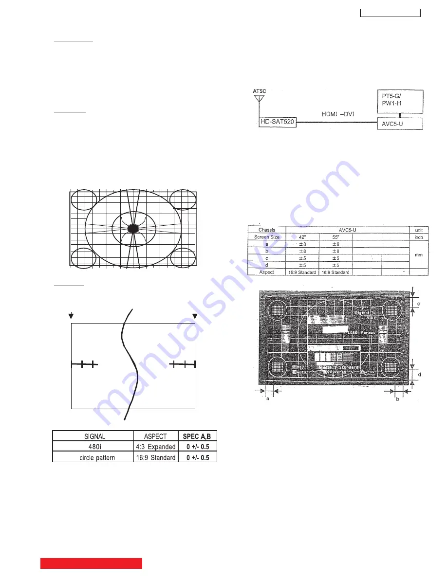
6. SCREEN CHECK
Preparation
(1) Set AC120±1V.
(2) Turn on the power and leave it more than 5 min.
(3) Receive circle pattern at 4:3 Expanded mode.
(4) Input 480p and 1080i circle pattern into Component
1. (ASPECT 16:9 Standard)
(5) Input XGA (60Hz) circle pattern into RGB. (ASPECT
Full)
Checking
(1) Receive RF, 480p, 1080i and XGA (60Hz) signal,
then check the following items 1~4:
1. Check the symmetry of the pattern (right/left).
2. Check the horizontal position and the balance
(right/left).
3. Check the symmetry of the pattern (top/bottom).
4. Check the vertical position and the balance
(top/bottom).
Remarks
(1) RGB: XGA (60Hz).
( )
3
SCREEN
0 1 2
2 1 0
A
B
7. HDMI adjustment
a. DVI compatibility check
Preparation
1. Prepare HDTV signal generator.
2. Select 1080i format
3. Connect HDMI-DVI cable to the DVI input on the
AVC.
b. DVI/HDCP/Timing (Display Position) Check
1. Set 1080i crosshatch with black background,
with a small color bar and small multi-burst.
(Confirm that the picture appears as shown
below)
2. Press “INFO” button on remote control to
confirm that “1080i Format” indication appears.
3. Confirm that Horizontal and Vertical position
meet the following spec.
BACK TO ADJUSTMENTS
8. FACTORY RESET
After all of the adjustments of main chassis are finished,
perform FACTORY RESET.
(1) Enter Adjustment Mode by the method described in
sub-items 1-1 and 1-2 from page 30. (“Adjustment
Procedure Start-up”).
(2) From the first menu in Adjustment Mode, select
FACT RESET adjustment code.
(3) Activate FACT RESET by pressing “Right” cursor
key once.
(4) Check that the receiving channel goes to CH03.
Unit is set to factory settings.
(5) This procedure returns user settings to the values
and states shown in Table 1 on the following pages.
Summary of Contents for 42HDT51M
Page 12: ...12 PT5 G PW1 H TABLE OF CONTENTS Specification Features A Plasma ...
Page 13: ...13 PT5 G PW1 H ...
Page 14: ...14 PT5 G PW1 H B Environment ...
Page 15: ...15 PT5 G PW1 H ...
Page 16: ...16 PT5 G PW1 H ...
Page 30: ...30 PT5 G PW1 H 5 7 WHITE BALANCE ADJUSTMENT OSD FLOW DIAGRAM BACK TO ADJUSTMENTS ...
Page 32: ...32 PT5 G PW1 H 9 SETTING for Delivery ...
Page 33: ...33 PT5 G PW1 H 9 SETTING for Delivery continued ...
Page 34: ...34 PT5 G PW1 H 9 SETTING for Delivery continued ...
Page 35: ...35 PT5 G PW1 H 9 SETTING for Delivery continued ...
Page 36: ...36 PT5 G PW1 H 9 SETTING for Delivery continued ...
Page 53: ...53 PT5 G PW1 H 12 Circuit Block Diagram MONITOR ...
Page 54: ...54 PT5 G PW1 H MONITOR ...
Page 55: ...55 PT5 G PW1 H 12 Power Circuit Block Diagram MONITOR ...
Page 56: ...56 PT5 G PW1 H MONITOR ...
Page 57: ...57 PT5 G PW1 H 12 2 MPU Control Block Diagram MONITOR ...
Page 58: ...58 PT5 G PW1 H MONITOR ...
Page 64: ...FINAL WIRING DIAGRAM MONITOR 64 PT5 G PW1 H ...
Page 65: ...FINAL WIRING DIAGRAM MONITOR 65 PT5 G PW1 H ...
Page 66: ...FINAL WIRING DIAGRAM MONITOR 66 PT5 G PW1 H ...
Page 67: ...FINAL WIRING DIAGRAM MONITOR 67 PT5 G PW1 H ...
Page 95: ...AVC5U 95 PRINTED CIRCUIT BOARDS AV P W B CS TABLE OF CONTENTS ...
Page 96: ...96 AVC5U PRINTED CIRCUIT BOARDS AV P W B SS TABLE OF CONTENTS ...
Page 97: ...97 AVC5U PRINTED CIRCUIT BOARDS CONTROL P W B TABLE OF CONTENTS ...
Page 98: ...98 AVC5U PRINTED CIRCUIT BOARDS HDMI P W B CS TABLE OF CONTENTS ...
Page 99: ...99 AVC5U PRINTED CIRCUIT BOARDS HDMI P W B SS TABLE OF CONTENTS ...
Page 100: ...100 AVC5U PRINTED CIRCUIT BOARDS SW P W B SS TABLE OF CONTENTS ...
Page 101: ...101 PT5 G PRINTED CIRCUIT BOARDS FILTER P W B CS TABLE OF CONTENTS ...
Page 102: ...102 PT5 G PRINTED CIRCUIT BOARDS FILTER P W B SS TABLE OF CONTENTS ...
Page 103: ...103 PT5 G PRINTED CIRCUIT BOARDS LED P W B TABLE OF CONTENTS ...
Page 104: ...104 PT5 G PRINTED CIRCUIT BOARDS SIGNAL AUDIO P W B CS TABLE OF CONTENTS ...
Page 105: ...105 PT5 G PRINTED CIRCUIT BOARDS SIGNAL AUDIO P W B SS TABLE OF CONTENTS ...
Page 106: ...106 PT5 G PRINTED CIRCUIT BOARDS SW P W B TABLE OF CONTENTS ...
Page 107: ...107 PT5 G PW1 H ...
Page 108: ...108 PT5 G PW1 H ...
Page 131: ......


