- 5 -
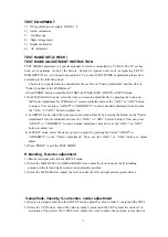
TEST EQUIPMENT
1) DC regulated power supply PAB18-1.8
2) Audio voltameter
3) Oscilloscope
4) High-voltage meter
5) Digital multimeter
6) AC voltameter
TEST MODE SET(CHECK)
TEST MODE ADJUSTMENT INSTRUCTION
TEST MODE adjustment is a special adjustment which is controlled by I
2
C BUS. The TV set has
been set at optimum mode at the factory. Except for special need, such as replacing CRT
、
MEMORY
、
IC etc., it is hoped not to adjust it. To conduct TEST MODE's adjustment, please do it
according to the following steps:
There are two special romote controller for the set. One is "Under Adjustment" and the other is
"Under Adjustment for W/B Balance".
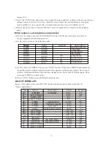
1) Press "PROD" button to enter the FACTORY, B/W BALANCE, ADJUST or SETUP mode.
2) In B/W BALANCE mode, select the item you want to adjust directly by pressing the button on
the"Under Adjustment for W/B Balance" remote controller and use the "ADJ+" or "ADJ-" button
to adjust. You can press "ADJUP" or "ADJDOWN" to select needed adjustment item and use
the "ADJ+" or "ADJ-" button to adjust too.
3) In ADJUST mode, select the item you want to adjust directly by pressing the button on the "Under
Adjustment" remote controller and use the "ADJ+" or "ADJ-" button to adjust. You can press
"ADJUP" or "ADJDOWN" to select needed adjustment item and use the "ADJ+" or "ADJ-"
button to adjust too.
4) In SETUP mode, select the item you want to adjust by pressing the button "ADJUP" or
"ADJDOWN" on the "Under Adjustment". Then use the "ADJ+" or "ADJ-" button to adjust.
adjust.
5) Press "PROD" to exit the TEST MODE.
H-blanking, H-center adjustment
1) Receive test signal, enter into the ADJUST mode.
2) Select the H.BLK.LEFT and H.BLK.RIGHT item, adjust the level to make the H -blanking
amount on the left and right screen at an appropriate position.
3) Select the H.PHASE item, adjust the level to make the left and right picture sysmmetrical.
V-amplitude, linearity, S-correction, center adjustment
1) Receive test signal, enter into the ADJUST mode. adjust the value to make V-center and the CRT's
2) Select the V.POS item , adjust the value to make V-center and the CRT's geometric center is in
accordance. Then select the V.SIZE item, adjust the value to make the overscan is less than or
Summary of Contents for TC14FS68
Page 13: ... 12 ...
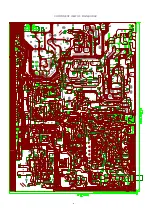
Page 17: ...COMPONENT VIEW OF MAIN BORAD 16 ...
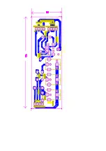
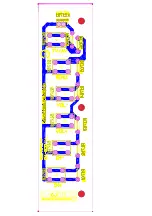
Page 18: ......
Page 19: ......
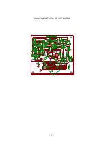
Page 20: ...COMPONENT VIEW OF CRT BORAD 18 ...
Page 21: ...COMPONENT VIEW OF STEREO BORAD 20 ...
Page 33: ...NO DESCRIPTION UNIT QTY LOCATION Page 11 of 22 ...


