- 3 -
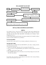
THE ALIGNMENT FLOW CHART
INSTALLATION AND SERVICE ADJUSTMENTS
GENERAL
In the majority of cases, a color television receiver will need only slight touch-up adjustment upon
installation. Check the basic characteristics such as FS
、
EHV and focus. Observe the picture for
good black and white details without objectionable color shading. If color shading is evident,
demagnetize the receiver.
If color shading still persists, perform purity and convergence adjustments. This should be all that is
necessary to achieve optimum receiver performance.
FOCUS ADJUSTMENT
Adjust the FOCUS control (on T471) for well defined scanning lines on the picture screen.
HIGH VOLTAGE CHECK
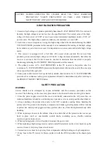
CAUTION: These is no HIGH VOLTAGE ADJUSTMENT on this chassis. Checking should be
done following the steps below.
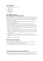
1. Connect an accurate high voltage meter to the second anode of the picture tube.
2. Turn on the receiver. Set the BRIGHTNESS and CONTRAST controls to minimum (zero beam
current).
3. High voltage will be measured about 28.5kV.
4. Vary the BRIGHTNESS control to both extremes to be sure the high voltage does not exceed the
limit under any conditions.
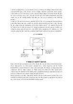
FS CIRCUIT CHECK
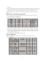
The Fail Safe (FS) circuit check is indispensable for the final check in the servicing. Checking
should be done following the steps below.
PIF
B+, AGC,H-frequency
To fit the front cabinet,
external degaussing
Preheat for 30 minutes
Factory items’
adjustment
Focus
Heatrun for 2 hours
White balance re-alignment, focus, high
voltage,
To fit the back cabinet
X-ray protection test, sound power test, CCD, V-chip,
BTSC, secret code setting, AV function check.
Control buttons, channels, white balance, sound, hit the set
Summary of Contents for TC14FS68
Page 13: ... 12 ...
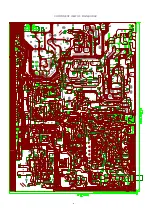
Page 17: ...COMPONENT VIEW OF MAIN BORAD 16 ...
Page 18: ......
Page 19: ......
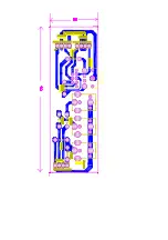
Page 20: ...COMPONENT VIEW OF CRT BORAD 18 ...
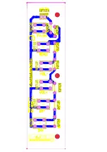
Page 21: ...COMPONENT VIEW OF STEREO BORAD 20 ...
Page 33: ...NO DESCRIPTION UNIT QTY LOCATION Page 11 of 22 ...


