- 4 -
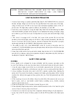
1. Turn the power switch on and adjust customer controls for normal operation.
2. Temporarily short R412 on the Main Board with a jumper wire. Raster and sound will
disappear.
3. The receiver must remain in this state even after removing the jumper wire. This is the evidence
that the FS circuit is functioning properly.
4. To obtain a picture again, temporarily turn the receiver off and allow the FS circuit more than 30
seconds to reset. Then turn the power switch on to produce a normal picture.
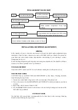
Troubleshooting Guide for Fail Safe Circuit
YES NO
NO
YES
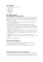
PIF alignment
1) Apply DC 12V to output pin of N551(pin3 of N551 ) , connect pin7 of LA76814(N101)
to GND.
2) Apply 95dB
μ
, 45.75MHz RF signal to the tuner's IF pin through a 1000P ceramic
capacitor. Connect the DC voltameter's
⊕
pole to LA76814 pin 47 ,
⊙
pole to GND.
Note:
For LA76814 ES01 version, the voltameter's
⊕
pole should connect to pin50 .
3) Adjust T202 with a non-inductive screwdriver until the reading on the DC voltameter is DC
3.6V
±
0.01V.
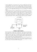
B+ CHECK
1) Prepare the test equipment.
2) Use the DC voltameter at DC 200V position to test VD551
⊕
, i.e. B+.
3) Connect the power plug to AC 120V/60Hz, turn on the power switch, wait for normal raster,
then adjust RP551 to make B+ = 110V
±
0.5V.
Test point
VD551
⊕
VD556
⊕
VD554
⊕
VD555
⊕
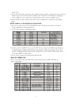
DC(V) 110 25 15 18
Check that the set returns to normal operation when pin
34 of N101 on the Main Board is grounded with jumper
Faulty
Power Circuit or Horizontal Circuit
Check if the voltage across capacitor
C411 is approximately 21V.
Defective Fail Safe Circuit
Summary of Contents for TC14FS68
Page 13: ... 12 ...
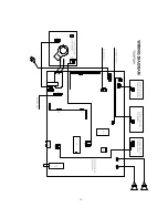
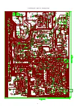
Page 17: ...COMPONENT VIEW OF MAIN BORAD 16 ...
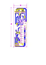
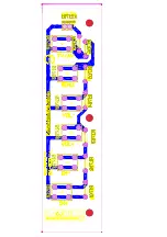
Page 18: ......
Page 19: ......
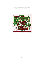
Page 20: ...COMPONENT VIEW OF CRT BORAD 18 ...
Page 21: ...COMPONENT VIEW OF STEREO BORAD 20 ...
Page 33: ...NO DESCRIPTION UNIT QTY LOCATION Page 11 of 22 ...


