Pressure Sensing
© Hirschmann Rev. I 05/22/17
190154_I.DOC
11
7 PRESSURE SENSING
The System measures the pressure of the boom lift cylinder for both rod- and piston-side. Both
sensors are contained within one box that also contains the electronics needed for amplification and
creation of the CAN-Bus signal.
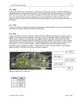
Block Diagram:
The signal runs from the pressure transducer as
digital information on the CAN-Bus to the central
unit.
7.1
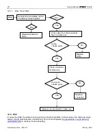
PRESSURE SENSING ERROR - FLOW CHART
Note: After exchanging the pressure transducer block, BOTH transducer channels need to be zeroed,
see procedure
Zero-Setting The Transducer Inputs
.
iFLEX5
CU
Pressure Transducer
(2)
Pressure-
Measuring
Cells
CAN-Bus
Converter
Pressure Sensing Error
First, verify the pressure displayed through the
console by using the sensor output screen.
Press the info
button twice
Pressure transducers are
functioning correctly.
Does the
displayed value
differ from the
actual value?
The readout should
read 500mV (+/-
25mV) and 0 PSI.
If the reading is slightly off, small variations can be adjusted;
see section Service Screen For Sensor Calibration.
NO
Ensure that the pressure lines
are drained and disconnected.
Replace pressure transducers.
YES


