iFLEX5 Boom Control System (BCS)
© Hirschmann Rev. I 05/22/17
190154_I.DOC
27
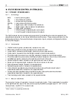
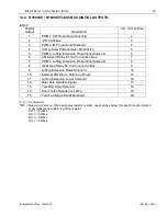
14.4 RT9000E / RT800E IFLEX5 BCS DIGITAL OUTPUTS:
table 2
Digital
Output
Description
C.U. X2 Terminal
1
PWM 1 CM Proportional Solenoid
2
2
+UB CAN bus
3
3
PWM 2 IM Proportional Solenoid
4
4
+UB to Slew Potentiometer Electronics
5
5
PWM 3 Luffing Extension Proportional Solenoid
6
6
CM Extend Relay K1 Coil in Junction Box
7
7
PWM 4 Luffing Extension Proportional Solenoid
8
8
IM Extend Relay K2 Coil in Junction Box
9
9
Luffing Extension Raise Solenoid
14
10
External LMI Alarm, Option on Boom
15
11
Luffing Extension Lower Solenoid
16
12
Rear Axle Oscillate Signal
17
13
Tele Rod Drain Solenoid
18
14
Boom Out of Sequence Lamp
19
15
Tele Two Stage Relief Solenoid
20
*C.U. = Central Unit
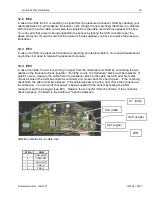
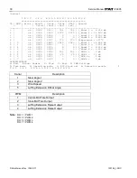
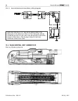
**MP = Measuring Point; i.e. R89 designates resistor number; see sketches below for specific location; Notes:
must measure on bottom leg of the resistor.
DO 1 = PWM 1
DO 3 = PWM 2
DO 5 = PWM 3
DO 7 = PWM 4


