Service Manual
iFLEX5
© Hirschmann Rev. I 0522/17
190154_I.DOC
24
14 IFLEX5 BOOM CONTROL SYSTEM (BCS)
14.1 RT9000E / RT800E BASICS
14.1.1
Terminology:
BCS
= boom control system
IM
= innermid boom section
CM
= center-mid boom section
OM/Fly
= outer-mid and fly boom section
DI
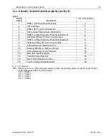
= digital input, refer to table 3 for definitions
DO
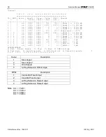
= digital output, refer to table 4 for definitions
PWM
= pulse width modulation
0
= off with regard to digital inputs and outputs
1
= on with regard to digital inputs and outputs
The BCS controls the boom telescoping sequence by controlling the current supplied to the
proportional solenoids on the 4-way directional control valves. These valves provide oil to the
telescoping cylinders. Here are the basic components, inputs, outputs, and logical functions
to make this happen.
14.1.2
Components:
iFLEX5 control system (central unit), located in the cab.
BCS relay junction box assy, located on rear exterior of cab.
Cable reel to measure overall length, located on boom base section.
Cable reel to measure inner-mid length, located on boom base section.
Proximity switch to sense inner-mid fully retracted, located on boom base section.
Proximity switch to sense center-mid fully retracted, located on boom inner-mid section.
Auto/Manual switch, located on the right hand arm rest in the cab.
Section selector switch, located on the right hand arm rest in the cab.
Boom out of sequence light, located on the front console in the cab.
Extend pressure switch, located on superstructure.
Retract pressure switch, located on superstructure.
Inner-mid pilot operated 4-way directional control valve with extend and retract
proportional solenoids, located on the superstructure.
Center-mid pilot operated 4-way directional control valve with extend and retract
proportional solenoids, located on the superstructure.
Tele two stage relief valve, located on the superstructure.
14.1.3
Manual / Auto Mode:
There are two modes of operation, manual or automatic mode. This is selectable by a switch
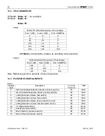
in the right hand arm rest in the cab, and is seen by the BCS as digital input 17. DI
1
17=0 is
manual mode. And DI 17=1 is auto mode.
1
Refer to table 1 for digital input definitions


